Induction heating device with dynamic spiral diversion and scale removal

The invention relates to an induction heating device and a technology of defouling by diversion, which is applied in the directions of fluid heaters, water heaters, lighting and heating equipment, etc., and can solve the problems of affecting the heat exchange capacity of the heating pipe, increasing the processing cost of the heating pipe, and having limited effects. To achieve the effect of simple structure, prevent scale generation, and solve dry burning damage

Pending Publication Date: 2018-02-02
ZHONGSHAN GONGZHI NEW ENERGY TECH CO LTD
View PDF5 Cites 1 Cited by
  • Summary
  • Abstract
  • Description
  • Claims
  • Application Information

AI Technical Summary

Problems solved by technology

This technical solution has at least the following defects: ① It is necessary to carve a spiral guide groove on the outer wall of the heating pipe, which increases the processing cost of the heating pipe; ② Although the heating pipe is washed and decontaminated by setting the spiral guide groove, scale is reduced to a certain extent Precipitation on the surface of the h

Method used


Image

  • Induction heating device with dynamic spiral diversion and scale removal
  • Induction heating device with dynamic spiral diversion and scale removal
  • Induction heating device with dynamic spiral diversion and scale removal

Examples


Embodiment 1

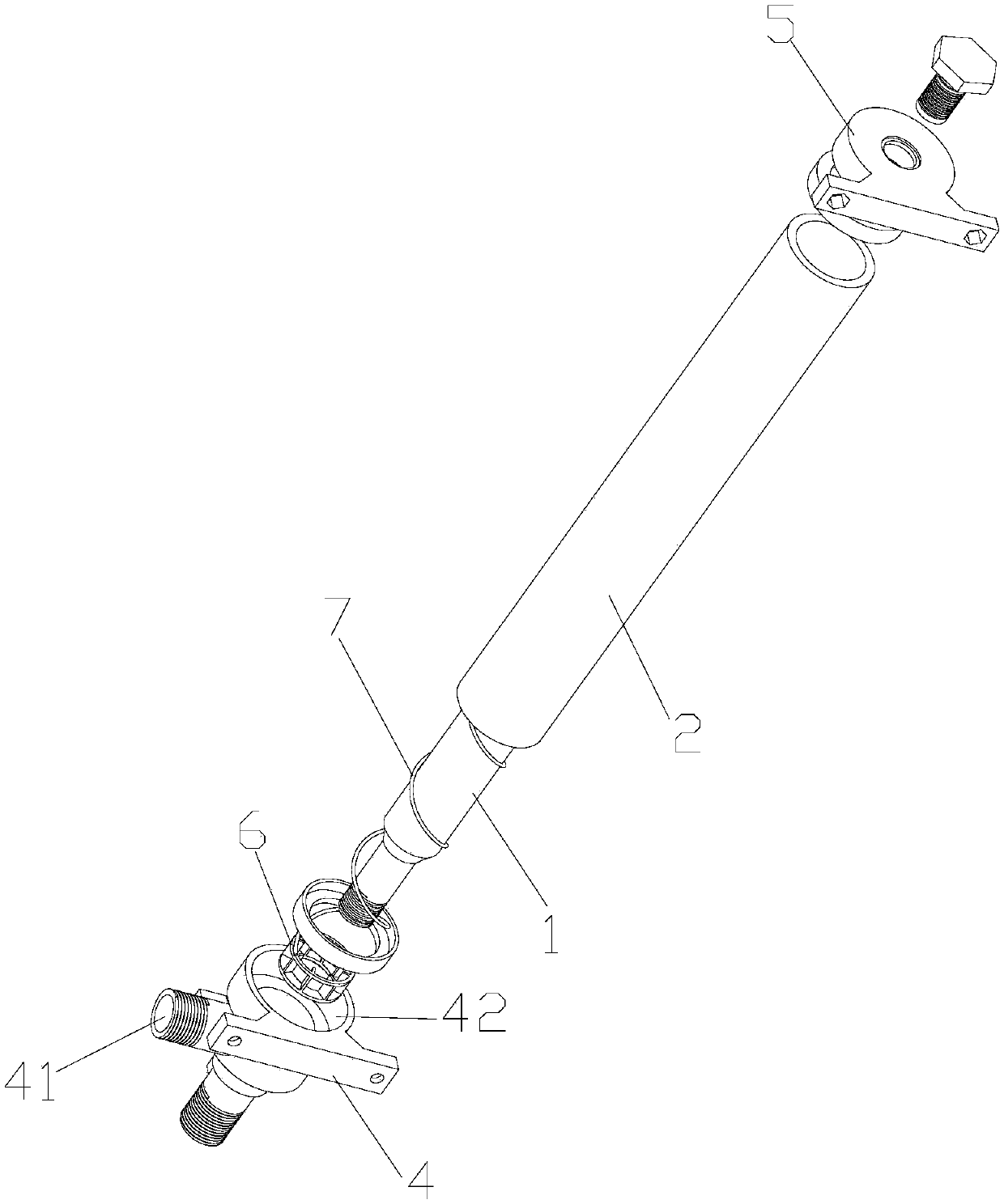
[0024] The rotating device 6 is a turbine (or impeller), and the turbine is arranged in the accommodation cavity 42 and sleeved on the lower end of the metal heat pipe 1 . Since the accommodating cavity 42 is facing the water inlet 41, when cold water enters the water inlet joint 4 from the water inlet 41, the flowing cold water drives the turbine to rotate, and during the rotation of the turbine, the cold water is driven to rotate, so that the cold water has a spiral force and The way of spiral rotation flows upward along the metal heating pipe 1 from the lower end of the heating chamber 8, and the cold water fully exchanges heat with the metal heating pipe 1 during the flow in the heating chamber 8, thereby being heated to become hot water.

[0025] Compared with the way in the prior art that the cold water directly flows upward from the lower end of the heating chamber 8, in this embodiment, the cold water is driven by the turbine to flow upward along the metal heating pipe ...

Embodiment 2

[0027] Since Embodiment 1 relies on the cold water that enters from the water inlet 41 to drive the turbine to rotate, the spiral force that the turbine can make the cold water have is limited, and it is difficult to ensure that the cold water still has sufficient force to prevent the generation of scale when it flows to the upper end of the heating chamber 8 Scouring force, so this embodiment is to add a power unit to the turbine, such as the power unit is a micro-motor, the rotating shaft of the micro-motor is connected with the turbine drive according to the actual situation, driving the turbine to run at a larger speed, increasing the spiral force that the cold water has Size, when guaranteeing that cold water flows to the upper end of heating chamber 8, still have enough to prevent the scouring force that produces scale.

Embodiment 3

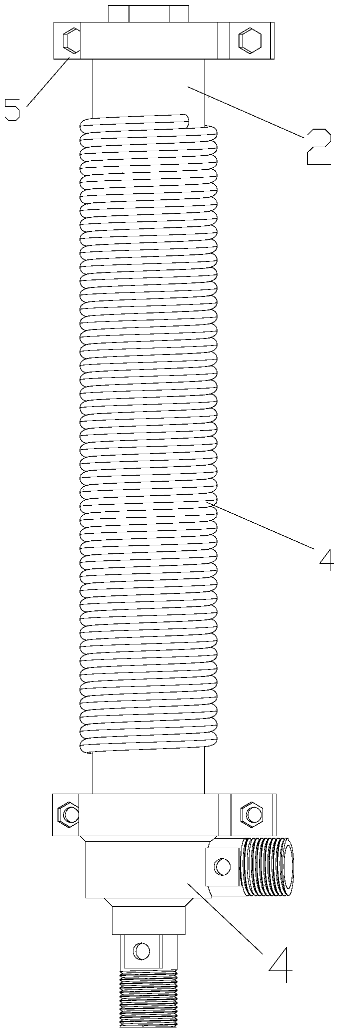
[0029] The heating chamber 8 is provided with a helical guide part 7 wound helically on the metal heating tube 1, and the lower end of the helical guide part 7 is fixedly connected with the rotating device 6; the rotating device 6 is a turbine or an impeller. Moreover, since the part of the metal heating tube 1 located in the heating chamber 8 is cylindrical with the same outer diameter, the inner diameter of the spiral guide part 7 is 2 to 10 mm larger than the outer diameter of the metal heating tube 1, so that the spiral guide part 7 is closely attached to the outer surface of the metal heating pipe 1.

[0030] When the rotating device 6 rotates, it drives the spiral guide part 7 to rotate synchronously. The spiral guide part 7 not only provides guidance for the cold water to move upward from the lower end of the heating chamber 8, but also clings to the metal heating tube during the rotation process. The outer surface of 1 rotates, and during the rotation, foreign matter s...


PUM


Abstract

The invention discloses an induction heating device with dynamic spiral diversion and scale removal. The induction heating device comprises a metal heating tube used for induction heating, an insulating sleeve which sleeves outside the metal heating tube, a water inlet joint and a rotary device, wherein a heating cavity is provided between the metal heating tube and the insulating tube; the waterinlet joint is used for fixing the lower tail end of the metal heating tube to the lower tail end of the insulating sleeve, and is provided with a water inlet; the rotary device is used for driving cold water entering from the water inlet to flow upwards in a spiral mode from the lower tail end of the heating cavity along the metal heating tube; and the rotary device is arranged on the bottom of the heating cavity, and sleeves the lower tail end of the metal heating tube. The induction heating device is simple in structure, is extremely good in water and scale removal effect, and even can prevent the metal heating tube from generating water scales, so that heat conduction ability and reliability of the induction heating device are improved.

Description

technical field [0001] The invention relates to an induction heating technology, in particular to an induction heating device with dynamic spiral guide flow descaling. Background technique [0002] Chinese patent CN2015205367799 proposes a detachable and cleanable electromagnetic heating device for water heaters. The outer wall of the heating pipe is also provided with a spiral guide groove for the spiral rise of the water in the water inlet channel. Since the water is a spiral rise, its On the one hand, it can effectively and automatically clean the scale that may exist on the outer surface of the heating tube, and on the other hand, its heating is more uniform. This technical solution has at least the following defects: ① It is necessary to carve a spiral guide groove on the outer wall of the heating pipe, which increases the processing cost of the heating pipe; ② Although the heating pipe is washed and decontaminated by setting the spiral guide groove, scale is reduced to...

Claims


Application Information

Patent Timeline
IPC IPC(8): F24H1/10F24H9/18F24H9/00
CPCF24H1/101F24H9/0021F24H9/1818F24H2250/08
Inventor 陈兆峰吕永王俐权
Owner ZHONGSHAN GONGZHI NEW ENERGY TECH CO LTD
Why Eureka
Try Eureka