
Rotary conductive apparatus

A technology of conducting device and conducting rod, applied in the direction of rotating current collectors, circuits, current collectors, etc., to achieve the effect of high conductivity reliability

Active Publication Date: 2018-02-02
YUNAN JINGCHUANG LIQUID METAL THERMAL CONTROL TECH RES & DEV CO LTD
View PDF3 Cites 2 Cited by
  • Summary
  • Abstract
  • Description
  • Claims
  • Application Information

AI Technical Summary

Problems solved by technology

[0006] The invention provides a rotating conductive device to solve the problem in the prior art that it is necessary to frequently clean the conductive device or replace some accessories in the conductive device during the power transmission process between relatively rotating workpieces.

Method used


Image

  • Rotary conductive apparatus
  • Rotary conductive apparatus
  • Rotary conductive apparatus

Examples


Embodiment Construction

[0026] The specific implementation manners of the present invention will be further described in detail below in conjunction with the accompanying drawings and embodiments. The following examples are used to illustrate the present invention, but are not intended to limit the scope of the present invention.

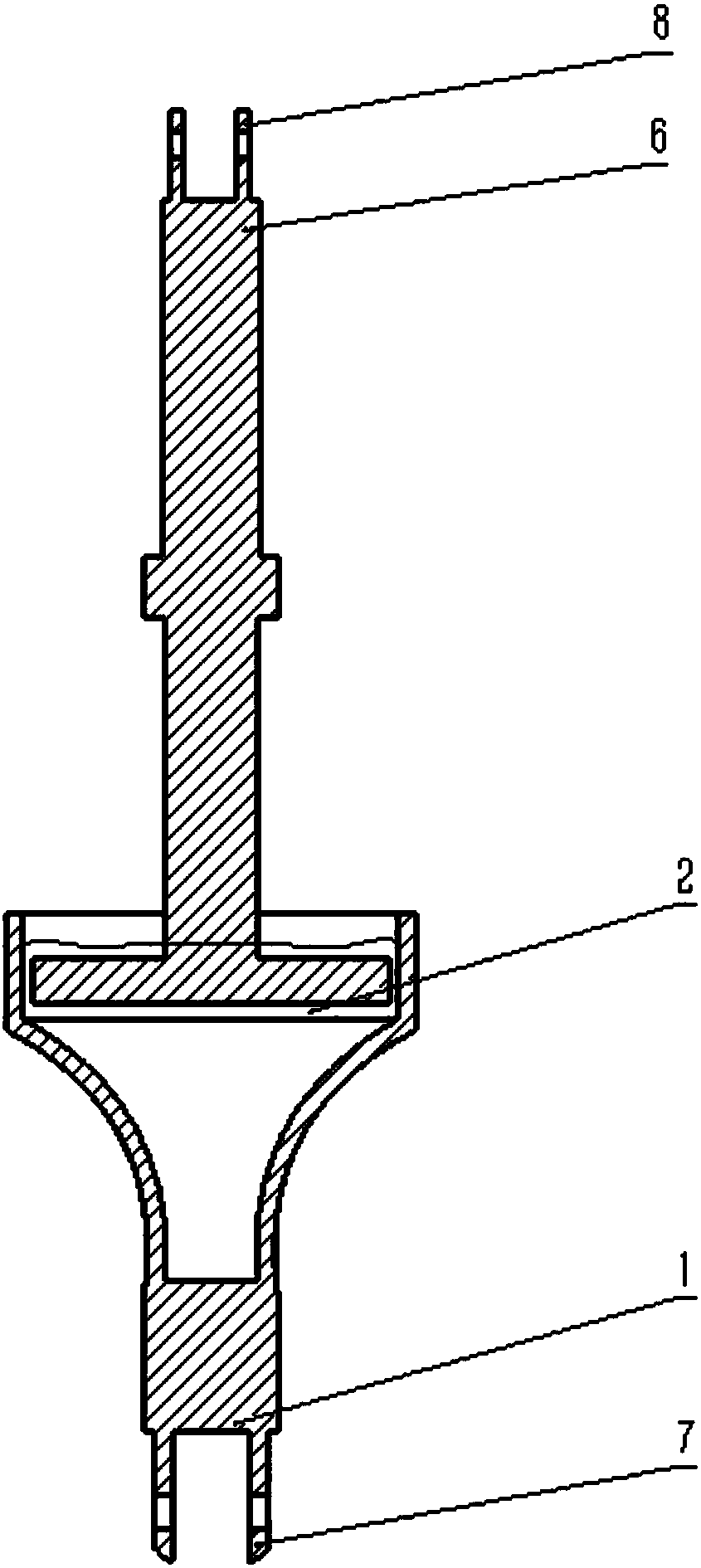
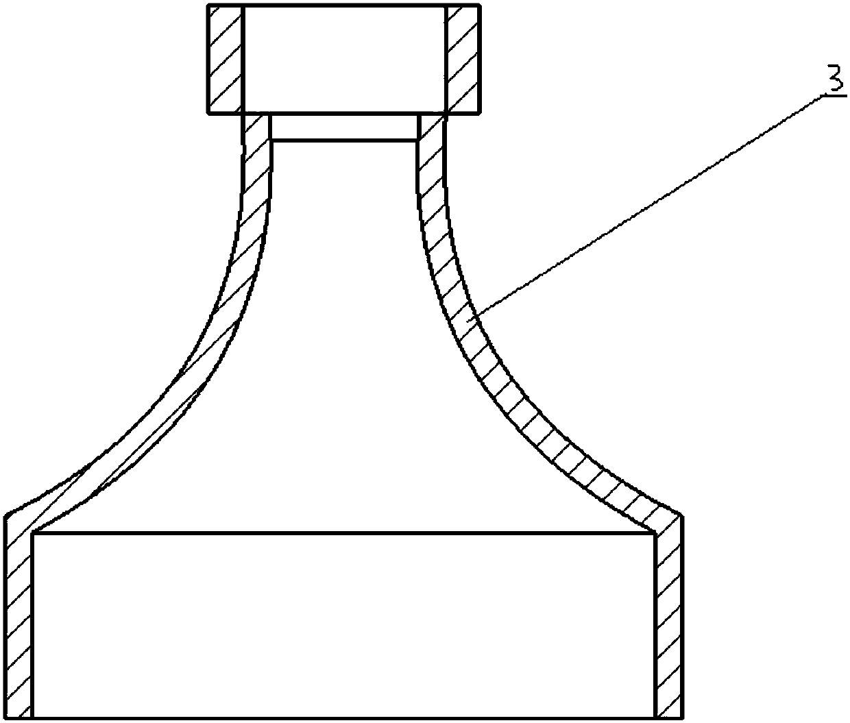
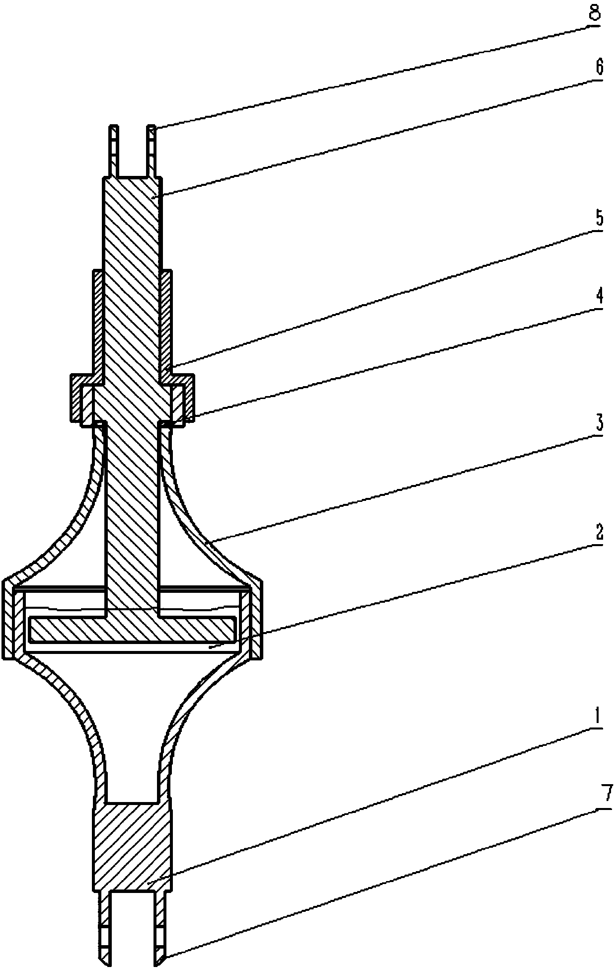
[0027] figure 1 To provide a schematic structural diagram of a rotating conductive device according to an embodiment of the present invention, as shown in figure 1 As shown, the device includes: a cup body 1, liquid metal 2 is placed in the cup body 1, a first terminal 7 is provided at the bottom end of the cup body, and the first terminal 7 is used to connect the first Workpiece; conductive rod 6, the conductive rod 6 is used to transmit electric energy, the bottom end of the conductive rod is placed in the liquid metal 2, the top of the conductive rod is provided with a second terminal 8, the second terminal 8 is used to connect the second workpiece.

[0028] Specific...


PUM


Abstract

The invention provides a rotary conductive apparatus. The rotary conductive apparatus comprises a cup body and a conductive rod, wherein liquid-state metal is arranged in the cup body; a first wiringend is arranged at the bottom end of the cup body; the first wiring end is used for connecting a first workpiece; the conductive rod is used for transmitting electric energy; the bottom end of the conductive rod is placed in the liquid-state metal; a second wiring end is arranged at the top end of the conductive rod; and the second wiring end is used for connecting a second workpiece. According tothe rotary conductive apparatus provided by the invention, the cup body and the conductive rod are connected with different workpieces; the bottom end of the conductive rod is placed in the liquid-state metal; the electric energy transmitted by the conductive rod is transferred to the cup body through the liquid-state metal, so that electric energy transmission between workpieces in different working states can be realized; and in addition, by adoption of the liquid-state metal conductive mode, the apparatus is high in conductive reliability and easy to maintain, and accessories can be replaced easily.

Description

technical field [0001] The invention relates to the field of electrical structural equipment, and more specifically, to a rotating conductive device. Background technique [0002] In the field of electrical structural equipment, there are many requirements for multiple relative motions such as revolution and rotation between electrical components, that is, a workpiece that rotates continuously at 360° needs to transmit energy or signals to another workpiece that is stationary or does not rotate synchronously with it. The movement of electrical components requires the provision of energy, such as electrical energy, fluid pressure energy, etc. [0003] In the circuit connection structure of rotating equipment, many wiring problems will affect the normal conduction and use of the equipment. When two electrical components that rotate relative to each other are electrically connected, the existing wire connection method will cause the two electrical components to wind the wires ...

Claims


Application Information

Patent Timeline
Patent Type & Authority Applications(China)
IPC IPC(8): H01R39/64
CPCH01R39/646
Inventor 董鑫盛磊刘静
Owner YUNAN JINGCHUANG LIQUID METAL THERMAL CONTROL TECH RES & DEV CO LTD
Learn More