Low-cost high-reliability position detecting device of permanent-magnet synchronous motor

A permanent magnet synchronous motor and detection device technology, applied in the direction of electronic commutator, etc., can solve the problems of increasing the difficulty of fault judgment, increasing sensor faults, etc., and achieve the effects of improving work reliability, reducing failure probability and reducing costs.

Pending Publication Date: 2018-02-02
NINGBO INST OF MATERIALS TECH & ENG CHINESE ACADEMY OF SCI
View PDF15 Cites 2 Cited by
  • Summary
  • Abstract
  • Description
  • Claims
  • Application Information

AI Technical Summary

Problems solved by technology

Therefore, the above methods are not low-cost, and the use of multiple sensor devices also increases the probability of sensor failure, and when there are interference signals entering, it increases the difficulty of fault judgment

Method used


Image

  • Low-cost high-reliability position detecting device of permanent-magnet synchronous motor
  • Low-cost high-reliability position detecting device of permanent-magnet synchronous motor
  • Low-cost high-reliability position detecting device of permanent-magnet synchronous motor

Examples


Embodiment 1

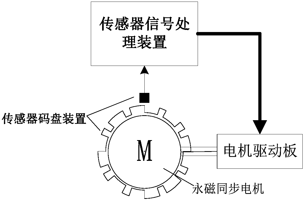
[0036] Such as figure 1 As shown, a low-cost and high-reliability permanent magnet synchronous motor position detection device in this embodiment includes a detection part that rotates synchronously with the motor, and is coupled with the detection part and outputs high and low levels according to the position state of the detection part. A single sensor, and a sensor signal processing device that receives the detection signal of the sensor and calculates the position information of the motor rotor.

[0037] In this embodiment, the detection part uses a suitable code disc to detect the position information of the rotor of the motor through a single sensor.

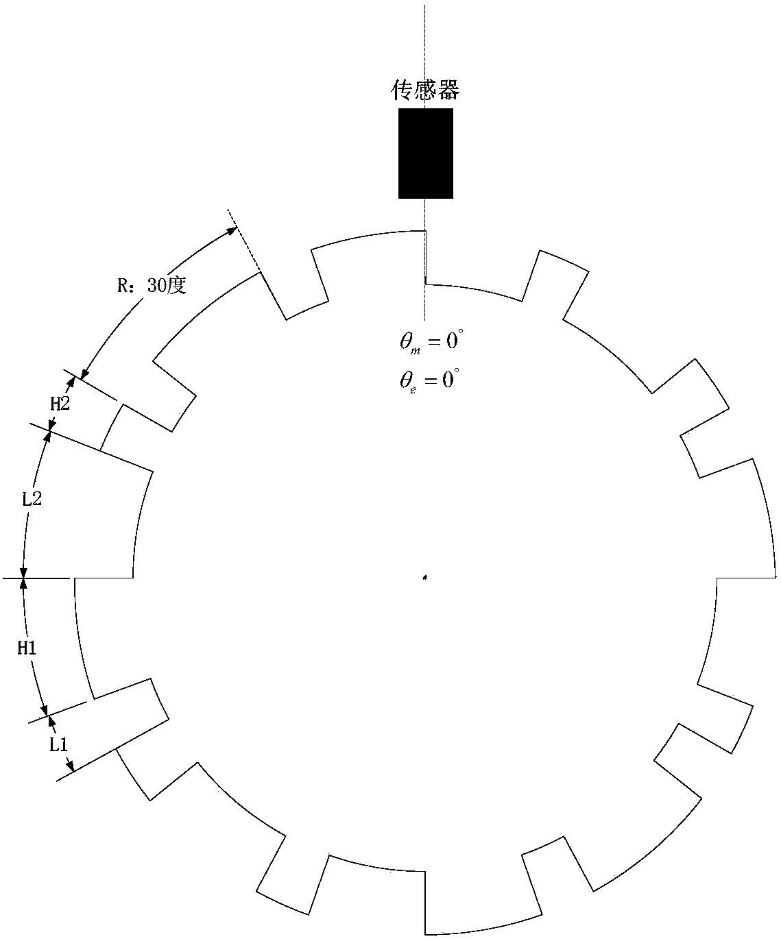
[0038] Such as image 3 A single sensor is shown and detects the corresponding code wheel. The code disc is a code disc matching a three-phase permanent magnet synchronous motor with 12 slots and 4 poles, and the code disc is coaxially fixed with the rotor of the motor. The convex part of the code wheel is indicated by ...

Embodiment 2

[0074] A low-cost and high-reliability permanent magnet synchronous motor position detection device in this embodiment includes a single sensor device and a sensor signal processing device. Compared with the first embodiment, this embodiment does not use a code disc, and the detection part uses the magnetic poles of the motor rotor. The sensor outputs a corresponding high-level or low-level detection signal according to the N magnetic pole or the S magnetic pole of the motor rotor. When the motor rotates, the sensor device outputs a series of square wave signals with the same width and width, which are input to the sensor signal processing device, and the position information is obtained after processing.

[0075] Such as Figure 12 As shown, the number of sensors in this embodiment is one, which is installed in a three-phase permanent magnet synchronous motor with 12 slots and 4 poles to detect the polarity change of the 4-pole rotor.

[0076] The sensor in this embodiment ...


PUM


Abstract

The invention discloses a low-cost high-reliability position detecting device of a permanent-magnet synchronous motor. The position detecting device comprises the components of a detecting part whichsynchronously rotates along with the electrical machine, a single sensor which is coupled with the detecting part and outputs a high level or a low level according to the position state of the detecting part, and a sensor signal processing device which receives the detecting signal and calculates position information of a motor rotor. According to the position detecting device, through utilizing the single sensor, and utilizing a code disc or a rotor magnetic pole as the detecting part of the sensor, performing coding calculation on the output signal of the sensor through the sensor signal processing device, the required electrical angle and mechanical angle position of the motor is obtained, thereby well reducing cost, reducing fault probability of the sensor and difficulty in determiningthe sensor fault, and improving operation reliability.

Description

technical field [0001] The invention relates to the field of permanent magnet synchronous motors, in particular to a position detection device for permanent magnet synchronous motors with low cost and high reliability. Background technique [0002] Permanent magnet synchronous motors need to collect position information during control, and the collection methods usually use photoelectric sensors, Hall sensors, rotary encoders, incremental encoders or absolute encoders. Among them, the cost of rotary encoders, incremental encoders and absolute encoders is relatively high, and the use of photoelectric sensors or Hall sensors requires multiple devices on the basis of traditional position detection methods. Therefore, the above methods are not low-cost, and the use of multiple sensor devices also increases the probability of sensor failure, and in addition, when an interference signal enters, it increases the difficulty of fault judgment. Contents of the invention [0003] Th...

Claims


Application Information

Patent Timeline
Patent Type & Authority Applications(China)
IPC IPC(8): H02P6/16
CPCH02P6/16
Inventor 虞冠杰蒋哲张驰乔海陈雪飞
Owner NINGBO INST OF MATERIALS TECH & ENG CHINESE ACADEMY OF SCI
Why Eureka
Try Eureka