
Voice controlled lamp time-delay switching circuit

A technology of time-delay switch and voice-activated lamp, which is applied in the direction of electric lamp circuit layout, electric light source, electrical components, etc., can solve the problems of high production cost, loud sound, poor sensitivity, etc., and achieve low cost, simple circuit, and good sensitivity Effect

Inactive Publication Date: 2018-02-02
苏州松挺材料科技有限公司
View PDF0 Cites 1 Cited by
  • Summary
  • Abstract
  • Description
  • Claims
  • Application Information

AI Technical Summary

Problems solved by technology

[0003] The purpose of the present invention is to overcome the problems of voice-activated lamps on the market, such as poor sensitivity, requiring a loud sound to trigger, complex circuits, high production costs, and inconvenient debugging.

Method used


Image

  • Voice controlled lamp time-delay switching circuit

Examples


Embodiment Construction

[0013] The present invention will be further described below in conjunction with the accompanying drawings.

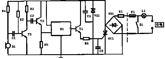
[0014] Such as figure 1 As shown, the voice-activated lamp delay switch circuit of the present invention includes a rectifier bridge circuit VD1, one input end of the rectifier bridge circuit VD1 is connected to the live wire of the mains through a current limiting resistor R1, and the other input end of the rectifier bridge circuit VD1 One input terminal is connected to the neutral line of the commercial power, and the positive output terminal of the rectifier bridge circuit VD1 is respectively connected to the positive pole of the thyristor VT1, the negative pole of the Zener diode VS1, the collector of the transistor T1, and the positive power supply terminal of the audio control chip U1 , the collector of the transistor T2, one end of the resistor R2, one end of the resistor R3, and one end of the resistor R4, the other end of the resistor R4 is connected to the ba...


PUM


Abstract

The invention discloses a voice controlled lamp time-delay switching circuit, which is characterized in that a rectifier bridge circuit VD1 and a thyristor VT1 form a switching main circuit, a time delay circuit is formed by an audio control chip U1 and a piezoelectric ceramic piece B1, the piezoelectric ceramic piece B1 picks up an acoustic signal when a user claps the hands or stamps the feet, then the acoustic signal is amplified by a transistor T3, a forward pulse is given out, the forward pulse is coupled to a base electrode of a transistor T2 by a capacitor to enable the transistor T2 tobe instantly conducted, the audio control chip U1 is triggered to operate by the high level of a trigger terminal, an output end outputs a music signal stored in the audio control chip U1, the musicsignal is amplified by a transistor T1 and then injected into a gate pole of the thyristor VT1 to enable the thyristor VT1 to be triggered into operation, the switching main circuit is conducted, a lighting lamp L1 is turned on, and the lighting lamp L1 is turned off when the music signal stored in the audio control chip is completely played. The voice controlled lamp time-delay switching circuitis simple, low in cost, free of programmed control and convenient to implement, and has good application prospects.

Description

technical field [0001] The invention relates to the technical field of control circuits, in particular to a voice-activated lamp delay switch circuit. Background technique [0002] Voice-activated lights are used to control the opening of the lights by sound. After the sound disappears, the lights will go out after a delay. They are widely used in corridors. At present, the sound-activated lights on the market have poor sensitivity and require a loud sound to trigger, and the circuit is complicated, the production cost is high, and the debugging is inconvenient. Contents of the invention [0003] The purpose of the present invention is to overcome the problems of poor sensitivity, need for a loud sound to trigger, complex circuit, high production cost and inconvenient debugging of the sound-activated lamps on the market. The voice-activated lamp delay switch circuit of the present invention collects sound by pressing a ceramic sheet, has good sensitivity, can be triggered...

Claims


Application Information

Patent Timeline
Patent Type & Authority Applications(China)
IPC IPC(8): H05B37/02
CPCH05B47/12H05B47/16
Inventor 周素华
Owner 苏州松挺材料科技有限公司
Learn More