Air inlet valve

An air intake valve and air source technology, applied in the field of compressors, can solve the problems of inability to realize continuous control of the exhaust volume of the compressor, inability to realize forced loading operation, inability to force loading, etc., achieving a simple structure and avoiding repeated loading and unloading. , easy to operate effect

Inactive Publication Date: 2018-02-06
SUZHOU SULLAIR GAS EQUIP
View PDF7 Cites 0 Cited by
  • Summary
  • Abstract
  • Description
  • Claims
  • Application Information

AI Technical Summary

Problems solved by technology

[0003] Existing intake valves often include a valve body and an air source control valve. A valve body cavity is arranged in the valve body, and both ends of the valve body cavity are opened. An air inlet valve core is provided between the air inlet end and the air outlet end of the body cavity. The valve body cavity includes a first drive chamber and a second drive chamber. One end of the air source control valve communicates with the first drive chamber to control the air source. Enter the first drive chamber through the air source control valve to drive the intake valve core to move to increase the opening, and the other end of the air source control valve is connected with the second drive chamber so that the control air source enters the second drive chamber through the air source control valve The cavity drives the intake valve core to move to reduce the opening until it is closed. The air source control valve is connected to the first drive cavity and the second drive cavity; it has the disadvantage that it cannot be forced to load. If the compressor uses this intake valve, it will When the compressor is integrated into the compressor pipe network for operation, the forced loading operation in the online state cannot be realized when the gas demand of the pipe network is needed, and the continuous control of the displacement of the compressor cannot be realized. An additional host computer is required to control each compressor. The machine is loaded and unloaded repeatedly, easy to wear and tear

Method used


Image

  • Air inlet valve

Examples


Embodiment Construction

[0018] In order to make the object, technical solution and advantages of the present invention clearer, the present invention will be further described in detail below in conjunction with the accompanying drawings and embodiments. It should be understood that the specific embodiments described here are only used to explain the present invention, not to limit the present invention.

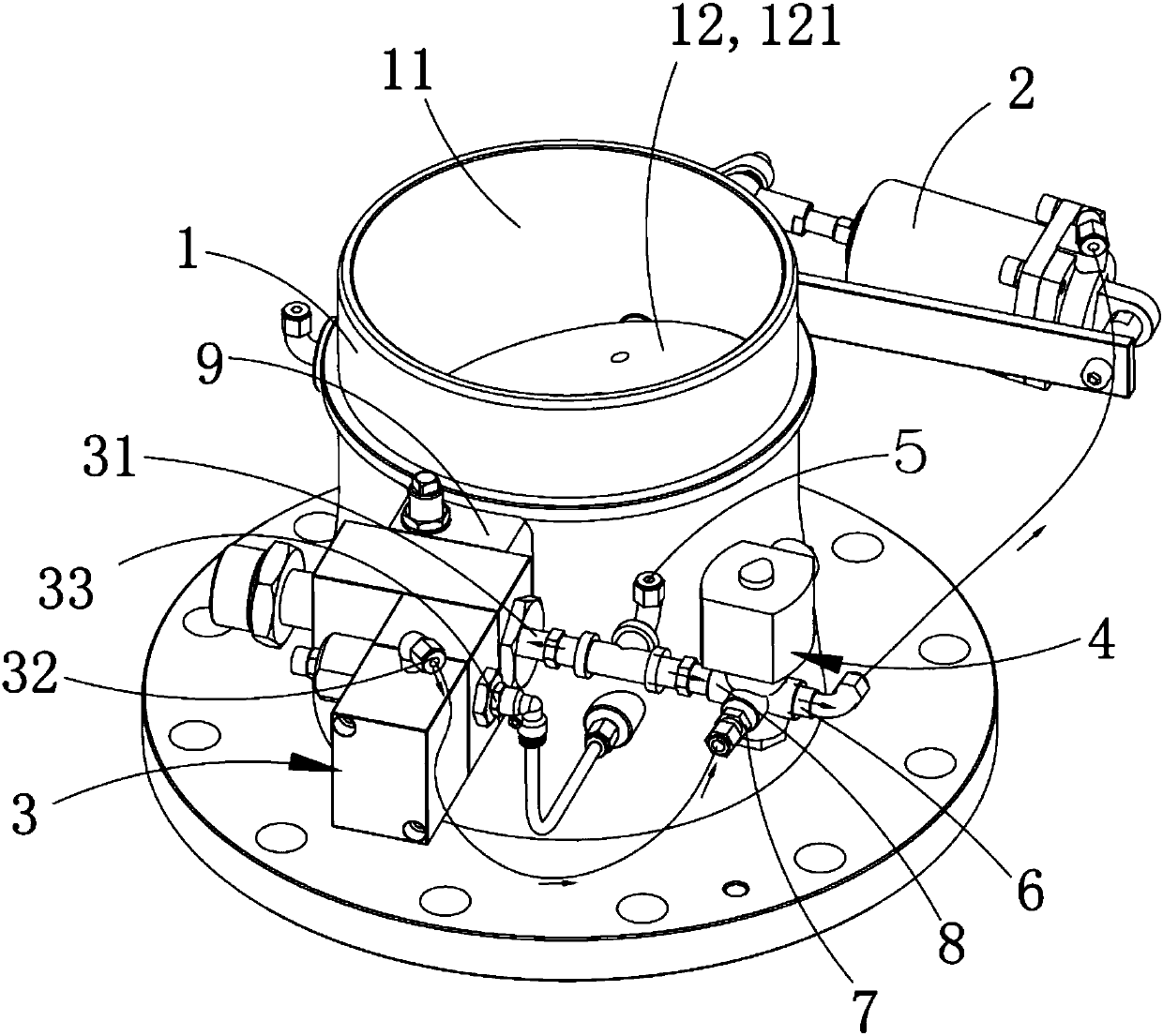
[0019] Such as figure 1 As shown, the intake valve provided in this embodiment includes an intake valve core 12, a cylinder 2, an air source control valve 3, a valve body 1 for connecting to a compressor, and a valve body chamber 11. The valve body chamber 11 includes a control air source The first drive chamber that moves the intake valve core 12 to increase the intake opening and the second drive cavity that accommodates the control air source to move the intake valve core 12 to reduce the intake opening, the air source control valve The air inlet 31 is connected to the air source inlet 5, the f...


PUM


Abstract

The invention provides an air inlet valve which comprises a valve body, a valve body cavity, an air inlet valve element, an air cylinder, an air source control valve and an online control valve. An air inlet of the air source control valve is connected with an air source inlet. A first air outlet of the air source control valve, a first air flow path and the air cylinder are communicated in sequence. A second air flow path is connected between the air source inlet and the air cylinder. The valve body cavity comprises a first drive cavity commutating with the air cylinder and a second drive cavity connected with a second air outlet of the air source control valve. The online control valve comprises the first air flow path and the second air flow path. When a compressor is in unit operationor grid-connected operation, the first air flow path is opened or closed, and the second air flow path is closed or opened. The structure is simple, and operation is easy; the online control valve isadditionally arranged, the first air flow path can be selected to be opened when the compressor is in unit operation so that the air inlet quantity can be adjusted; when the compressor is in grid-connected operation, the second air flow path can be selected to be opened so that the air inlet valve can achieve continuous air inputting, forced loading is carried out on the compressor, and repeated loading and unloading are avoided; and safety and reliability are achieved, and cost is low.

Description

technical field [0001] The invention belongs to the technical field of compressors, and in particular relates to an intake valve. Background technique [0002] The main purpose of on-line control is to control the operation status of each compressor in the compressor group to meet the user's demand for gas consumption. The ideal state is that one compressor in the compressor group is in the adjustment state and the other compressors are in the forced loading state. [0003] Existing intake valves often include a valve body and an air source control valve. A valve body cavity is arranged in the valve body, and both ends of the valve body cavity are opened. An air inlet valve core is arranged between the air inlet end and the air outlet end of the body cavity, and the valve body cavity includes a first drive chamber and a second drive chamber, and one end of the air source control valve communicates with the first drive chamber to control the air source Enter the first drive ...

Claims


Application Information

Patent Timeline
Patent Type & Authority Applications(China)
IPC IPC(8): F04B39/08F04B39/10F04B49/22
CPCF04B39/08F04B39/102F04B49/225
Inventor 孙建刘毅张吉超李广彬
Owner SUZHOU SULLAIR GAS EQUIP
Why Eureka
Try Eureka