Supercharge Your Innovation With Domain-Expert AI Agents!

Frequency acquisition method of butterfly plate-valve rod assembly in butterfly valve for inducing vibration of fluid

An acquisition method and butterfly plate technology, applied in special data processing applications, instruments, electrical digital data processing, etc., can solve problems such as complex force characteristics of butterfly plates

Inactive Publication Date: 2018-02-06
UNIV OF SHANGHAI FOR SCI & TECH
View PDF3 Cites 0 Cited by
  • Summary
  • Abstract
  • Description
  • Claims
  • Application Information

AI Technical Summary

Problems solved by technology

This boss will cause unequal pressure on the two working surfaces of the fluid when it flows around the disc, as well as the shedding of the vortex and flow separation. more complex features

Method used


Image

  • Frequency acquisition method of butterfly plate-valve rod assembly in butterfly valve for inducing vibration of fluid
  • Frequency acquisition method of butterfly plate-valve rod assembly in butterfly valve for inducing vibration of fluid
  • Frequency acquisition method of butterfly plate-valve rod assembly in butterfly valve for inducing vibration of fluid

Examples


Embodiment 1

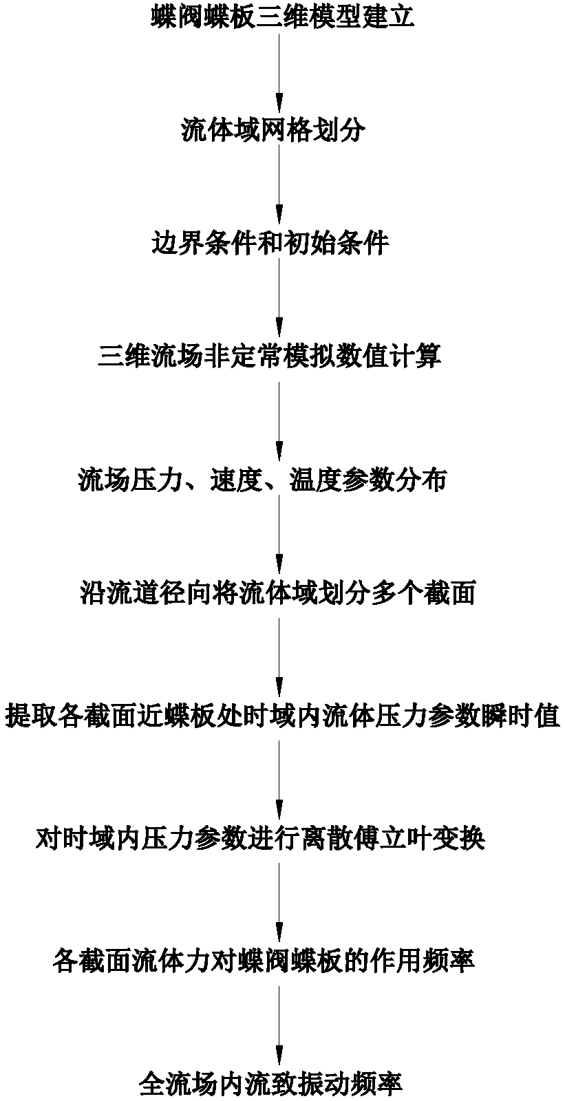
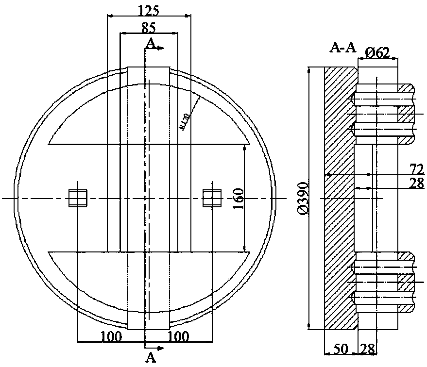
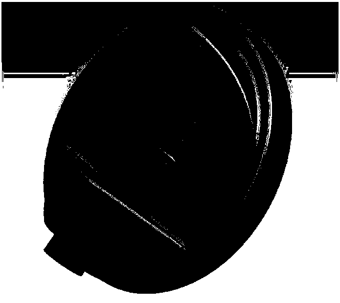
[0047] figure 1 is a schematic flow diagram of an embodiment of the present invention, figure 2 It is a two-dimensional structural diagram of the butterfly plate-valve stem assembly of the embodiment of the present invention, image 3 It is a three-dimensional structural diagram of the butterfly plate-valve stem assembly of the embodiment of the present invention, Figure 4 It is a schematic diagram of the calculation domain and the position of the butterfly plate-valve stem assembly in the calculation domain of the embodiment of the present invention, Figure 5 is the left view of the embodiment of the present invention Figure three The mesh at the eccentric butterfly plate, Figure 6 is the left view of the embodiment of the present invention Figure three Grid at the eccentric butterfly plate.

[0048] Table 1: Working condition parameter table

[0049]

[0050] Step 1, establish a three-dimensional model of the butterfly valve disc-stem assembly, see figure 2 an...

Embodiment 2

[0063] Step 1, establish a three-dimensional model of the butterfly valve disc-stem assembly, see figure 2 and image 3 . Determine the calculation domain and the position of the disc-stem assembly in the calculation domain, see Figure 4 . For the degree of mesh density and details of local mesh division near the butterfly plate and valve stem in the calculation domain, see Figure 5 and Figure 6 shown.

[0064] Step 2, using the actual working conditions of the fluid flowing through the butterfly plate-valve stem assembly shown in Table 1, the velocity and temperature values ​​at the initial moment of the inlet of the upstream pipe section, and the pressure and temperature values ​​at the initial moment of the outlet of the downstream pipe section are given, The three-dimensional unsteady numerical simulation calculation in the flow channel is carried out to obtain the distribution of parameters such as pressure, velocity and temperature in the flow field in the flow ...


PUM


Abstract

The invention discloses a frequency acquisition method of a butterfly plate-valve rod assembly in a butterfly valve for inducing vibration of fluid. The method includes the following steps of creatinga three-dimensional model of the butterfly plate-valve assembly in the butterfly valve, and conducting mesh partition on a fluid region of the fluid according to the opening degree of the butterfly valve; according to boundary conditions and initial conditions of actual working conditions when the fluid flows through the butterfly plate-valve rod assembly, conducting three-dimensional unsteady numerical simulation calculation of the interior of flow channels to obtain distribution of the flow parameters of the interior of each flow channel; according to the structural features of a butterflyplate, diving the fluid region into multiple sections with important features in radial directions of the flow channels, and selecting key monitoring points at the positions, close to the wall surfaceof the butterfly plate-valve rod assembly, on each section; conducting Fourier transform of discrete data on a pressure parameter instantaneous value to obtain fluid force acting frequency of the keymonitoring points of the sections.

Description

technical field [0001] The invention relates to the internal flow characteristics of a triple eccentric butterfly valve, and calculates the vibration frequency generated by a fluid induced by a butterfly plate-valve stem assembly, in particular to a method for acquiring the frequency of the fluid vibration induced by a butterfly plate-valve stem assembly in a butterfly valve. Background technique [0002] Fluid-induced structural vibration refers to the vibration of a structure in a fluid or transmitting a fluid. The reason for the vibration is the action of the fluid force on the structure, or the interaction between the fluid force and the structure. The pressure of the fluid force acts on the structure, causing the structure to vibrate. The vibration of the structure will change the fluid domain. The change of the fluid domain will cause the change of the fluid flow state, and the flow field will also change, resulting in the change of the fluid force acting on the structu...

Claims


Application Information

Patent Timeline
Patent Type & Authority Applications(China)
IPC IPC(8): G06F17/50
CPCG06F30/20
Inventor 王海民孔祥帅刘欢胡峰
Owner UNIV OF SHANGHAI FOR SCI & TECH
Features
  • R&D
  • Intellectual Property
  • Life Sciences
  • Materials
  • Tech Scout
  • Unparalleled Data Quality
  • Higher Quality Content
  • 60% Fewer Hallucinations
Learn More