System and method for laying underground cables or underground lines in the ground near the surface

A technology for underground pipelines and underground cables, applied in cable laying equipment, drilling equipment and methods, cable installation in underground pipelines, etc., can solve the problems of undesired flushing fluid, etc., and achieve the effect of reducing interference

Active Publication Date: 2018-02-06
HERRENKNECHT AG
View PDF7 Cites 8 Cited by
  • Summary
  • Abstract
  • Description
  • Claims
  • Application Information

AI Technical Summary

Problems solved by technology

In conventional HDD methods, laying depths in the range of less than 10 m can lead to undesired flushing in certain soil conditions

Method used


Image

  • System and method for laying underground cables or underground lines in the ground near the surface
  • System and method for laying underground cables or underground lines in the ground near the surface
  • System and method for laying underground cables or underground lines in the ground near the surface

Examples


Embodiment Construction

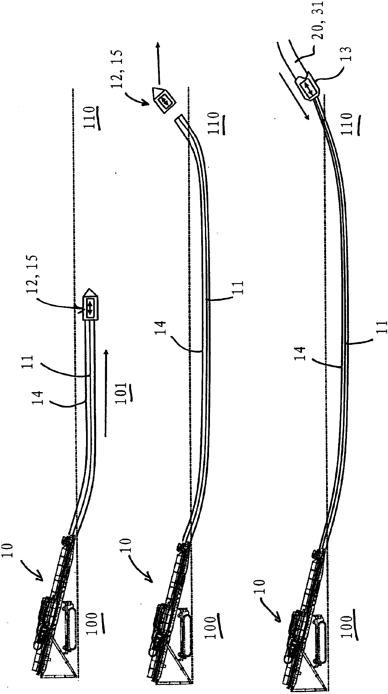
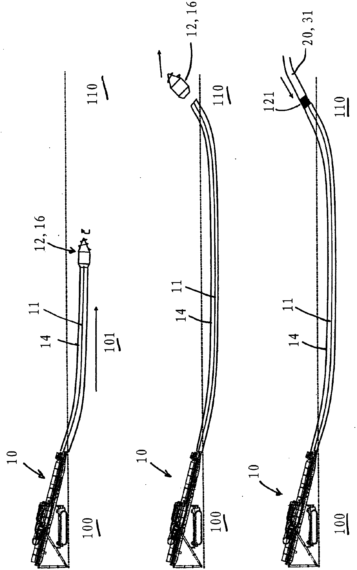
[0033] The HDD drilling device 10 is installed at the starting point 100 ( figure 1 , figure 2) and is connected to the jacking head 12 via the drill pipe 11. Furthermore, a casing 14 surrounding the drill pipe 11 is provided. With the torque and propulsion provided by the drilling device 10 , the jacking head 12 is pushed along the direction of the predetermined path 101 to the target point 110 .

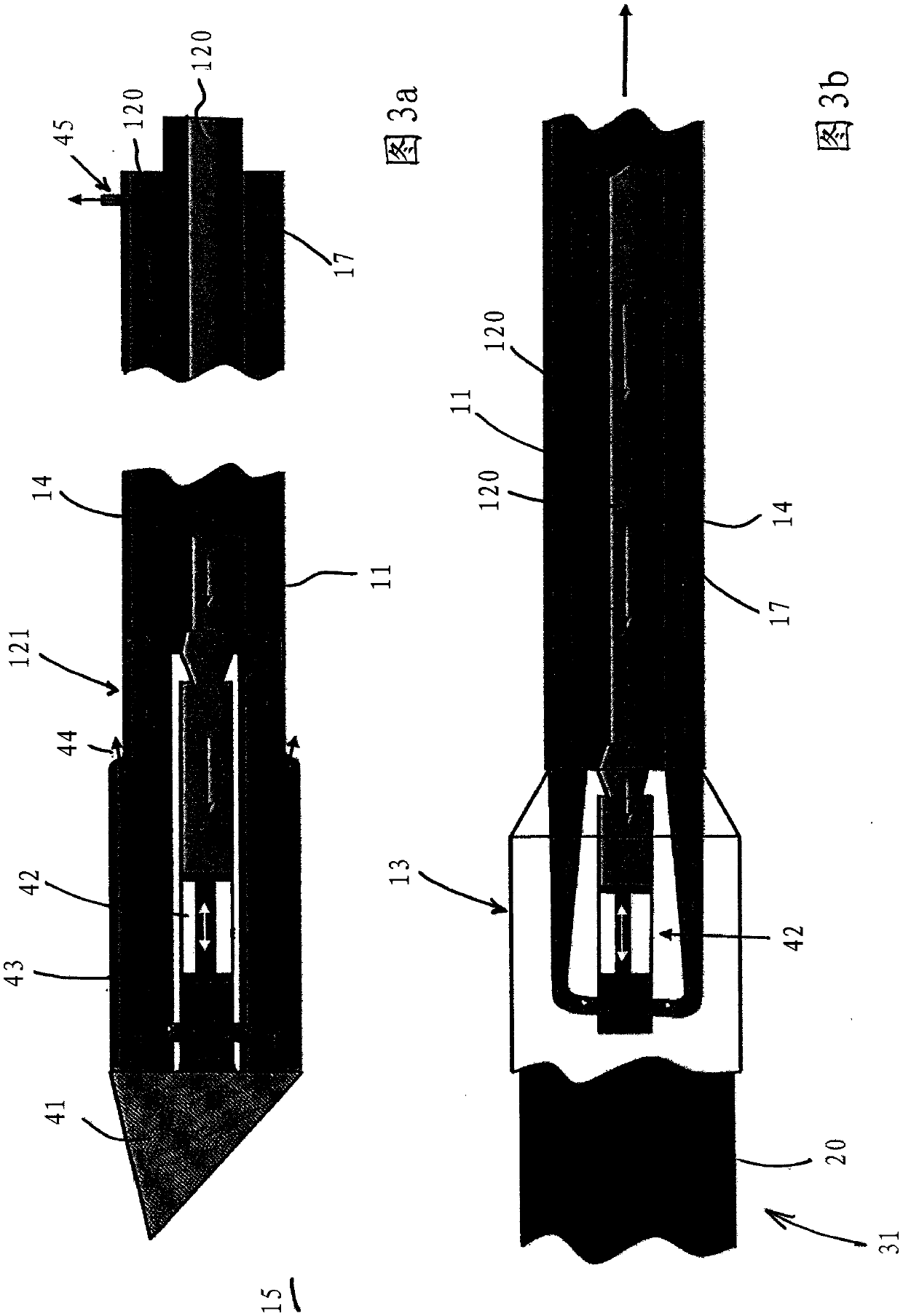
[0034] exist figure 1 A hammer drill 15 is shown and used as the jacking head 12 in FIG. The advancing movement takes place here via the sleeve 14 . The drill rod 11 is used for supplying flushing fluid for driving the drill hammer 15 and for rotating the drill hammer 15 , for example for control.

[0035] exist figure 2 A displacement screw 16 is provided as the jacking head 12 in the middle. The advancing movement takes place here via the sleeve 14 . The drill rod 11 is used to rotate the displacement screw 16 . The displacement screw can be controlled by supplying flu...


PUM


Abstract

The invention relates to a system for laying underground cables or underground lines in the ground near the surface, in a borehole (102) along a laying route (101) between a start point (100) and a target point (110), comprising a boring device (10) comprising an advancing head (12) for creating the borehole (102), a drilling rod (11) and / or a casing (14), wherein the diameter of the advancing head (12) is greater than the diameter of the casing (14) or of the drilling rod (11), so that an annular space (121) is formed between the borehole wall (102) and the casing (14) or the drilling rod (11) and the annular space (121) is provided with lubrication and wherein the advancing head (12) relates to a displacement drilling head (15, 16, 41) or a drilling head system (18) comprising a drillingtool (19) and a drilling tool drive (22) for loosening the ground.

Description

technical field [0001] The invention relates to a system for laying underground cables or pipelines near the surface in a borehole along a laying route between a starting point and a target point, the system having Drilling apparatus, a jacking head for making said borehole and having a drill pipe and / or casing, and the invention relates to a method for laying underground cables or pipelines near the surface in the ground, said Laying of underground cables or pipelines in boreholes along a laying route between a starting point and a target point, the method in which a jacking head is moved along said laying route by transmitting propulsion via a drill pipe with a drilling device Motion or transfer propulsion motion and rotation. Background technique [0002] When constructing a power grid, for example, when manufacturing 380kV pipelines, in addition to manufacturing power pipelines In addition, these pipelines also need to be laid underground. [0003] When laying underg...

Claims


Application Information

Patent Timeline
IPC IPC(8): E21B7/28E21B7/20E21B7/04H02G1/06H02G9/02
CPCE21B7/04E21B7/203E21B7/28H02G1/06H02G9/02E02F5/18E21B7/046E21B7/20E21B7/128H02G1/08H02G9/06
Inventor M·彼得斯T·恩格尔T·格哈特S·普雷托里乌斯
Owner HERRENKNECHT AG
Why Eureka
Try Eureka