CT inspection tester scanning bed structure and transmission method thereof

A technology of scanning bed and inspection instrument, which is applied in the field of CT scanning, can solve the problem of insufficient height fine-tuning ability, and achieve the effect of simple structure and stable lifting

Inactive Publication Date: 2018-02-09
无锡飞述科技有限公司
View PDF0 Cites 6 Cited by
  • Summary
  • Abstract
  • Description
  • Claims
  • Application Information

AI Technical Summary

Problems solved by technology

[0002] The CT scanning table is a tool for carrying the subject to complete the scanning task. It can realize the vertical motion control system and the horizontal and longitudinal motion. It can enter and exit the aperture of the scanning frame as required, and complete the scanning position of the automatic positioning detection object; the existing CT scanning Most of the lifting of the bed is driven by the principle of connecting rods, and the ability to fine-tune the height is insufficient

Method used


Image

  • CT inspection tester scanning bed structure and transmission method thereof
  • CT inspection tester scanning bed structure and transmission method thereof
  • CT inspection tester scanning bed structure and transmission method thereof

Examples


Embodiment Construction

[0018] The present invention will be further described below in conjunction with the accompanying drawings.

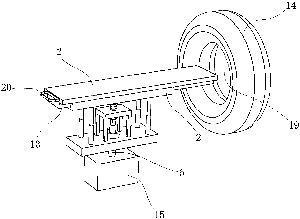
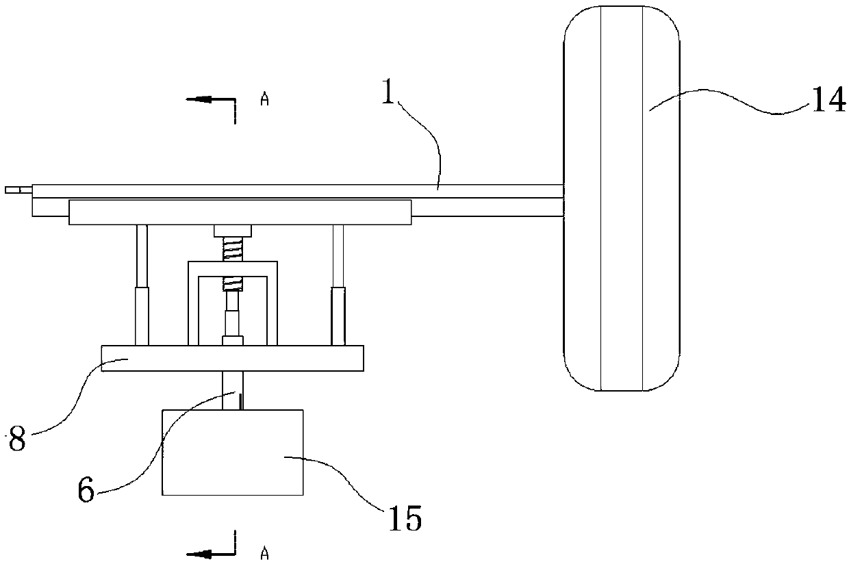
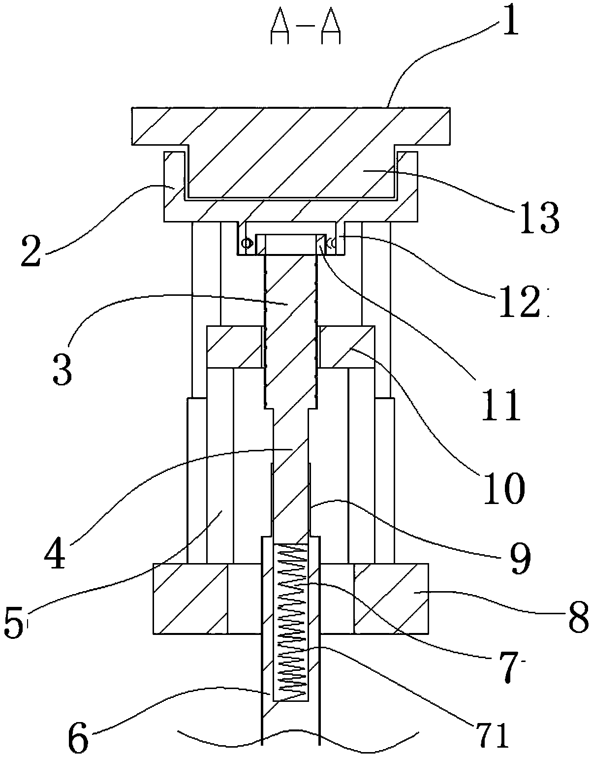
[0019] as attached Figures 1 to 4 As shown, a scanning bed structure of a CT examination instrument includes a scanning bed body 2, a bed body slider 13, a bed body slide rail 2, a base 8, a guide post 17, a guide cylinder 18, and a slide rail lifting mechanism;

[0020] The bed body slider 13 is fixedly arranged at the bottom of the scanning bed body 2; the bed body slider 13 is slidably arranged on the horizontally arranged bed body slide rail 2; the bottom four corners of the bed body slide rail 2 There are four guide pillars 17 vertically arranged at the center; the base 8 is fixedly arranged below the guide pillars 17, and four guide cylinders 18 are vertically fixedly arranged on the upper surface of the base 8; the four guide pillars The lower ends of 17 can be movably inserted into the four guide cylinders 18 respectively; The guide post 17 ensures that the ...


PUM


Abstract

The invention discloses a scanning bed structure of a CT examination instrument, which comprises a scanning bed body, a bed body slider, a bed body slide rail, a base, a guide post, a guide cylinder and a slide rail lifting mechanism; the bed body slider is fixedly arranged at the bottom of the scanning bed body; the bed body slider is slidably arranged on the horizontally arranged bed body slide rail; four guide columns are vertically arranged at four corners of the bottom of the bed body slide rail; The base is fixedly arranged under the guide pillars, and four guide cylinders are fixed vertically on the upper surface of the base; the lower ends of the four guide pillars can be inserted into the four guide cylinders respectively; the slide rail lifting mechanism Set between the four guide cylinders, the slide rail lifting mechanism can drive the slide rail of the bed body to move up and down; the structure of the present invention is simple, and the threaded rod is used to cooperate with the thrust bearing to realize the stable lifting of the scanning bed. The lifting height of the scanning bed can be controlled by controlling the rotation angle of the motor.

Description

technical field [0001] The invention belongs to the field of CT scanning, and in particular relates to a scanning bed structure and a transmission method of a CT examination instrument. Background technique [0002] The CT scanning table is a tool for carrying the subject to complete the scanning task. It can realize the vertical motion control system and the horizontal and longitudinal motion. It can enter and exit the aperture of the scanning frame as required, and complete the scanning position of the automatic positioning detection object; the existing CT scanning The lifting of the bed is mostly driven by the principle of connecting rods, and the ability to fine-tune the height is insufficient. Contents of the invention [0003] Purpose of the invention: In order to overcome the deficiencies in the prior art, the present invention provides a scanning bed structure of a CT examination machine, which can realize high-precision lifting of the scanning bed. [0004] Tech...

Claims


Application Information

Patent Timeline
Patent Type & Authority Applications(China)
IPC IPC(8): A61B6/04A61B6/03
CPCA61B6/0407A61B6/032
Inventor 唐霞云
Owner 无锡飞述科技有限公司
Why Eureka
Try Eureka