Spinal care massage device

A spine and massage table technology, applied in vibration massage, massage auxiliary products, physical therapy, etc., can solve the problems of uneven pressing pressure, inability to adjust the massage intensity, partial massage and full back massage can not be compatible at the same time, to achieve freedom High degree, improve the effect of massage effect

Active Publication Date: 2018-07-10
福建省同溢堂国医药发展有限公司
View PDF7 Cites 1 Cited by
  • Summary
  • Abstract
  • Description
  • Claims
  • Application Information

AI Technical Summary

Problems solved by technology

[0002] For spondylosis, the most commonly used treatment method is to massage the patient. The doctor presses the painful part with his hands or a massage device. The doctor's hand massage is labor-intensive. As the doctor's physical strength declines, the intensity Or gradually weakened, the pressing pressure is uneven, and the massage effect is not good
[0003] When using equipment to perform acupressure massage on a patient, an elastic sleeve is arranged on the upper end of the acupressure part, and then a mechanical device is used to drive the elastic sleeve to drive the acupressure part to move up and down continuously, so that the acupressure part is continuously pressed against the patient's back. For massage, if you need a wide range of massage, you need multiple finger pressure parts, and multiple finger pressure parts are connected to the driving device. When in use, multiple finger pressure parts massage the spine together. This equipment makes local Massage and full back massage cannot be compatible at the same time. A single shiatsu massage device can only perform partial massage, while multiple shiatsu massage devices can only move at the same time to achieve full back massage, which is inconvenient to use
And the existing massage equipment can only adjust the speed of the massage during the massage process, but cannot adjust the intensity of the massage, and the massage effect is not good

Method used


Image

  • Spinal care massage device
  • Spinal care massage device
  • Spinal care massage device

Examples


Embodiment 1

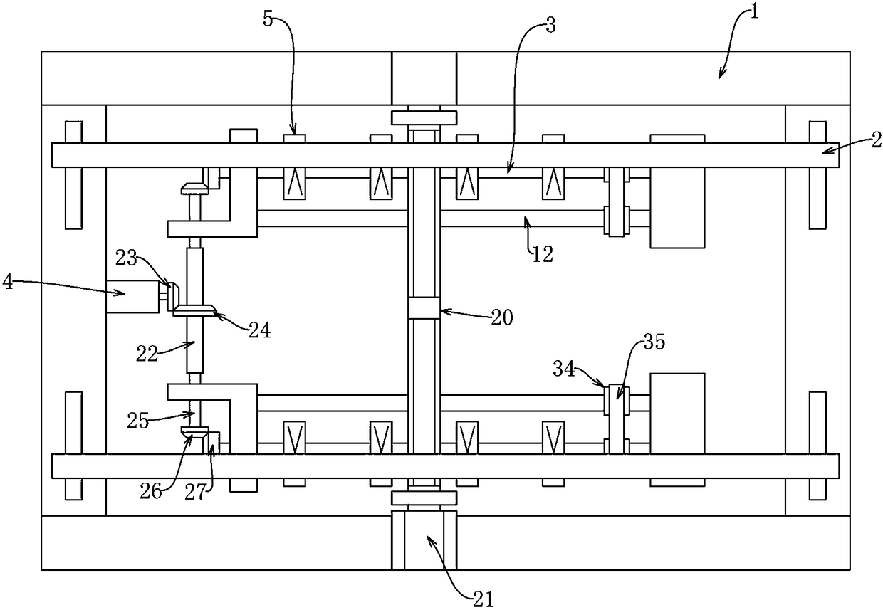
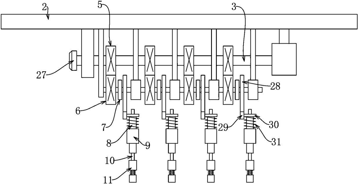
[0016] Embodiment 1, including a frame 1 placed above the massage bed, is characterized in that two mounting plates 2 extending along the length direction of the massage bed are provided on the frame 1 to slide along the width direction of the massage bed, and the two mounting plates 2 There is a distance adjustment device that can make the two mounting plates 2 approach or move away synchronously. The first rotating shaft 3 arranged along the length direction of the massage bed is rotatably connected to the bottom of the mounting plate 2. The speed regulating motor 4 is fixed on the frame 1. , the speed regulating motor 4 drives the first rotating shaft 3 through the elastic connection device that can cooperate with the distance adjusting device. The spacer sleeve on the first rotating shaft 3 has a plurality of first gears 5 inherent in it, and the bottom of the first gear 5 is engaged with a rotation connection The second gear 6 on the mounting plate 2, the second gear 6 is ...

Embodiment 2

[0017] Embodiment 2, on the basis of Embodiment 1, the frame 1 is connected with a positive and negative lead screw 20 rotating along the width direction of the bed body, and the positive and negative lead screws 20 of the positive and negative lead screw 20 are fitted with lead screw nuts respectively , the screw nuts are respectively connected to the two mounting plates 2, and the positive and negative screw screws 20 are connected with a rotating motor 21 to form a distance adjustment device. When in use, the motor 21 is rotated so that the positive and negative lead screws 20 rotate. Since the two mounting plates are respectively connected to the positive and negative leads of the positive and negative lead screws 20 through the lead screw nuts, the two mounting plates are close to or far away from each other. And it can be positioned and locked in real time, the two mounting plates move synchronously, and the moving distance is equal.

Embodiment 3

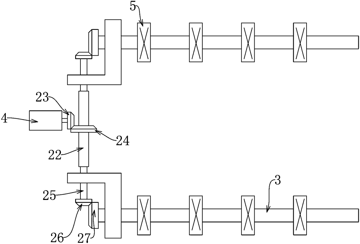
[0018] Embodiment 3, on the basis of Embodiment 2, a first sleeve 22 arranged along the width direction of the massage bed is provided in front of the speed-regulating motor 4, and a first bevel gear 23 is set on the speed-regulating motor 4, The first sleeve 22 is covered with a second bevel gear 24 that inherently meshes with the first bevel gear 23. The front and rear ends of the first sleeve 22 are respectively axially slidably connected with a first movable rod 25. The first The movable rod 25 is rotatably connected to the mounting plate 2. The first movable rod 25 is covered with a third bevel gear 26, and the first shaft 3 is covered with a fourth bevel gear 27 meshing with the third bevel gear 26. An elastic connection device that can cooperate with the distance adjustment device is formed. When the distance adjustment device makes the two mounting plates 2 approach or move away, the fourth bevel gear 27 is connected to the mounting plate 2 via the first rotating shaft...


PUM


Abstract

The invention provides a spine nursing and massaging device. Driving of massage parts and strength adjustment of massage columns are achieved through an adjustable-speed motor, strength adjustment canbe simultaneously conducted in the massage process of the massage columns, the device is beneficial to strength selection by patients, and the massage effect is improved; the gap between two rows ofmassage parts can be adjusted in the massage process, the positions of the massage parts can be optimal, and strength adjustment of massage and distance adjustment between two rows of massage parts are simultaneously conducted, so that the position and strength of massage are adjusted to be optimal. According to the spine nursing and massaging device, through the effect of an electromagnetic clutch, required massage parts can be randomly selected, a massage part can be selected, and multiple massage parts can also be selected at the same time; according to strength adjustment, the electromagnetic clutch can also be used for selecting the massage parts of which the strength needs to be adjusted, the degree of freedom is high, a control panel is arranged, and the patients control and adjustthe device conveniently according to self-conditions and feeling in the massage process.

Description

technical field [0001] The invention relates to a spinal care massage device. Background technique [0002] For spondylosis, the most commonly used treatment method is to massage the patient. The doctor presses the painful part with his hands or a massage device. The doctor's hand massage is labor-intensive. As the doctor's physical strength declines, the intensity Or gradually weaken, the pressing pressure is uneven, and the massage effect is not good. [0003] When using equipment to perform acupressure massage on a patient, an elastic sleeve is arranged on the upper end of the acupressure part, and then a mechanical device is used to drive the elastic sleeve to drive the acupressure part to move up and down continuously, so that the acupressure part is continuously pressed against the patient's back. For massage, if you need a wide range of massage, you need multiple finger pressure parts, and multiple finger pressure parts are connected to the driving device. When in us...

Claims


Application Information

Patent Timeline
Patent Type & Authority Patents(China)
IPC IPC(8): A61H23/02
CPCA61H23/006A61H23/02A61H2201/0142A61H2201/50A61H2205/081
Inventor 鲁花刘汝银岳宗进于露唐玲李云朋
Owner 福建省同溢堂国医药发展有限公司
Why Eureka
Try Eureka