Fire-fighting equipment

A fire extinguishing equipment and frame technology, applied in fire rescue and other directions, can solve the problems of loss, difficult fire control, and difficulty in transporting fire water to high places, etc., to achieve the effect of increasing coverage and more rescue time

Inactive Publication Date: 2018-02-09
北京市巨龙工程有限公司
View PDF6 Cites 2 Cited by
  • Summary
  • Abstract
  • Description
  • Claims
  • Application Information

AI Technical Summary

Problems solved by technology

Although the lifting heights of various types of fire trucks are constantly updated, they can only be extinguished by fixed fire extinguishing equipment inside the building after exceeding a certain height, and when a fire occurs, if there is a power failure or any part of the pipeline fails, it will be difficult to transport fire water to high places
At this time, it is difficult to control the fire, causing greater losses.

Method used


Image

  • Fire-fighting equipment
  • Fire-fighting equipment
  • Fire-fighting equipment

Examples


Embodiment 1

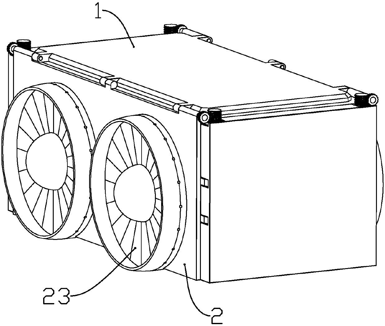
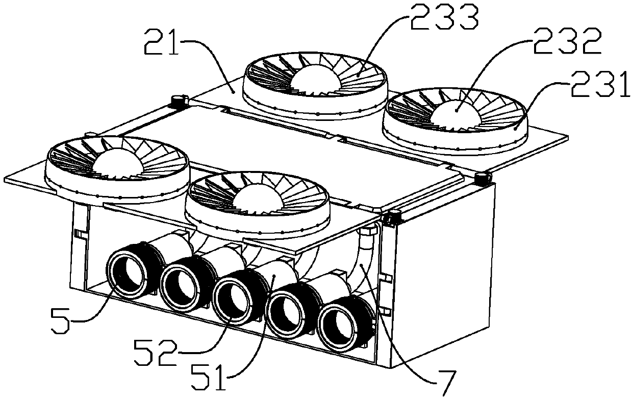
[0035] according to Figure 1 to Figure 8 As shown, this embodiment is a kind of fire extinguishing equipment, which includes a frame body 1 penetrating through the left and right sides, side plate assemblies 2 installed on the left and right sides of the frame body, a plurality of air injection pipes 7 installed in the frame body, and A plurality of guide assemblies 5 are respectively fixedly connected to one end of the jet pipe.

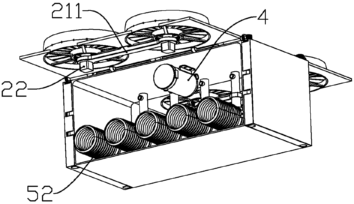
[0036] The side plate assembly includes a rotating plate 21 rotatably connected to the upper end of the frame and a fan assembly 23 mounted on the rotating plate; The mounting plate 211 of the assembly; the drive motor 22 for driving the fan assembly to rotate is installed on the mounting plate corresponding to the rotating shaft of the fan assembly; the outer edge of the fan assembly protrudes out of the rotating plate; The drive motor drives the entire fan assembly to rotate.

[0037] The fan assembly includes an inner ring 232 and an outer rin...

Embodiment 2

[0053] according to Figure 9 to Figure 11 As shown, this embodiment makes the following improvements on the basis of embodiment 1: the two ends of the rotating blades are respectively inserted into the inner ring and the outer ring; when all the rotating blades rotate to the same plane, the inner The ring is closed with the outer ring; the end of each rotating blade located in the inner ring is fixedly connected with a fourth gear 2331 .

[0054] An annular ultrasonic motor 234 coaxial with the fan assembly is installed in the inner ring; one end of the rotor of the annular ultrasonic motor faces each of the fourth gears; an annular disc is fixedly connected to the rotor of the annular ultrasonic motor 341 ; the end surface of the annular disc is formed with gear teeth meshing and drivingly connected with each of the fourth gears. Each of the rotating blades drives the fourth gear to rotate through the annular ultrasonic motor so as to rotate synchronously.

[0055] The rin...

Embodiment 3

[0058] This embodiment makes the following improvements on the basis of embodiment 1 or embodiment 2: the lower end of the frame body is detachably installed with electric grippers for grabbing high-pressure water guns or water pipes; connect. When encountering a fire, after installing the electric gripper, operate multiple devices to clamp the high-pressure water gun and the water pipe through the electric gripper and lift it up to spray the fire point to extinguish the fire. At the same time, it can also use the fire extinguishing ball to cooperate with the fire. The present invention can be controlled by only one person when extinguishing a fire, which reduces the input of personnel, so that more firefighters can participate in the rescue of the wounded; at the same time, by setting electric grippers, the equipment can spray fire extinguishing balls or pass fire Carry a high-pressure water gun for auxiliary fire extinguishing.


PUM


Abstract

The invention discloses fire-fighting equipment which comprises a frame body penetrating left and right, side plate assemblies mounted on the left and right sides of the frame body, a plurality of gasejector pipes mounted in the frame body and a plurality of guide assemblies fixedly connected to one ends of the gas ejector pipes correspondingly. Four supporting leg assemblies are mounted at the positions, close to the left and right ends, on the outer side walls of front and back ends of the frame body; and a gas pressurizing pump is mounted on the frame body. When a high pressure water gun cannot be used in high altitude fires or the needed prepared time is relatively long, a fire-fighting ball can be sprayed to the fired point remotely, so that more rescue time can be acquired.

Description

technical field [0001] The invention belongs to the field of fire safety, and in particular relates to a fire extinguishing device. Background technique [0002] High-rise fires are difficult to rescue due to the high location of the fire. Although the lifting heights of various types of fire trucks are constantly updated, they can only be extinguished by fixed fire extinguishing equipment inside the building after exceeding a certain height, and when a fire occurs, if there is a power failure or any part of the pipeline fails, it will be difficult to transport fire water to high places. Then it is difficult to control the fire at this time, causing greater losses. Contents of the invention [0003] The technical problem to be solved by the present invention is to provide a fire extinguishing device aiming at the deficiencies in the prior art. [0004] In order to achieve the purpose of the present invention, the following technical solutions are adopted: a fire extingu...

Claims


Application Information

Patent Timeline
Patent Type & Authority Applications(China)
IPC IPC(8): A62C19/00A62C31/00
CPCA62C19/00A62C31/00
Inventor 黄文佳
Owner 北京市巨龙工程有限公司
Why Eureka
Try Eureka