Optical lens polishing device and polishing process

A technology for optical lenses and polishing devices, which is applied to optical surface grinders, grinding/polishing equipment, manufacturing tools, etc., and can solve problems such as difficulty in ensuring lens surface shape and polishing accuracy, lens deformation, and low efficiency

Inactive Publication Date: 2018-02-09
II VI OPTICS (SUZHOU) CO LTD
View PDF0 Cites 7 Cited by
  • Summary
  • Abstract
  • Description
  • Claims
  • Application Information

AI Technical Summary

Problems solved by technology

[0004] The disadvantage of the traditional optical lens polishing process is that the operation is cumbersome and the efficiency is low. Due to the different conditions of the upper and lower plates, the lens is easily deformed due to elastic deformation during the process of the upper and lower plates, and it is difficult to ensure the surface shape and polishing accuracy of the lens.

Method used


Image

  • Optical lens polishing device and polishing process

Examples


Embodiment approach

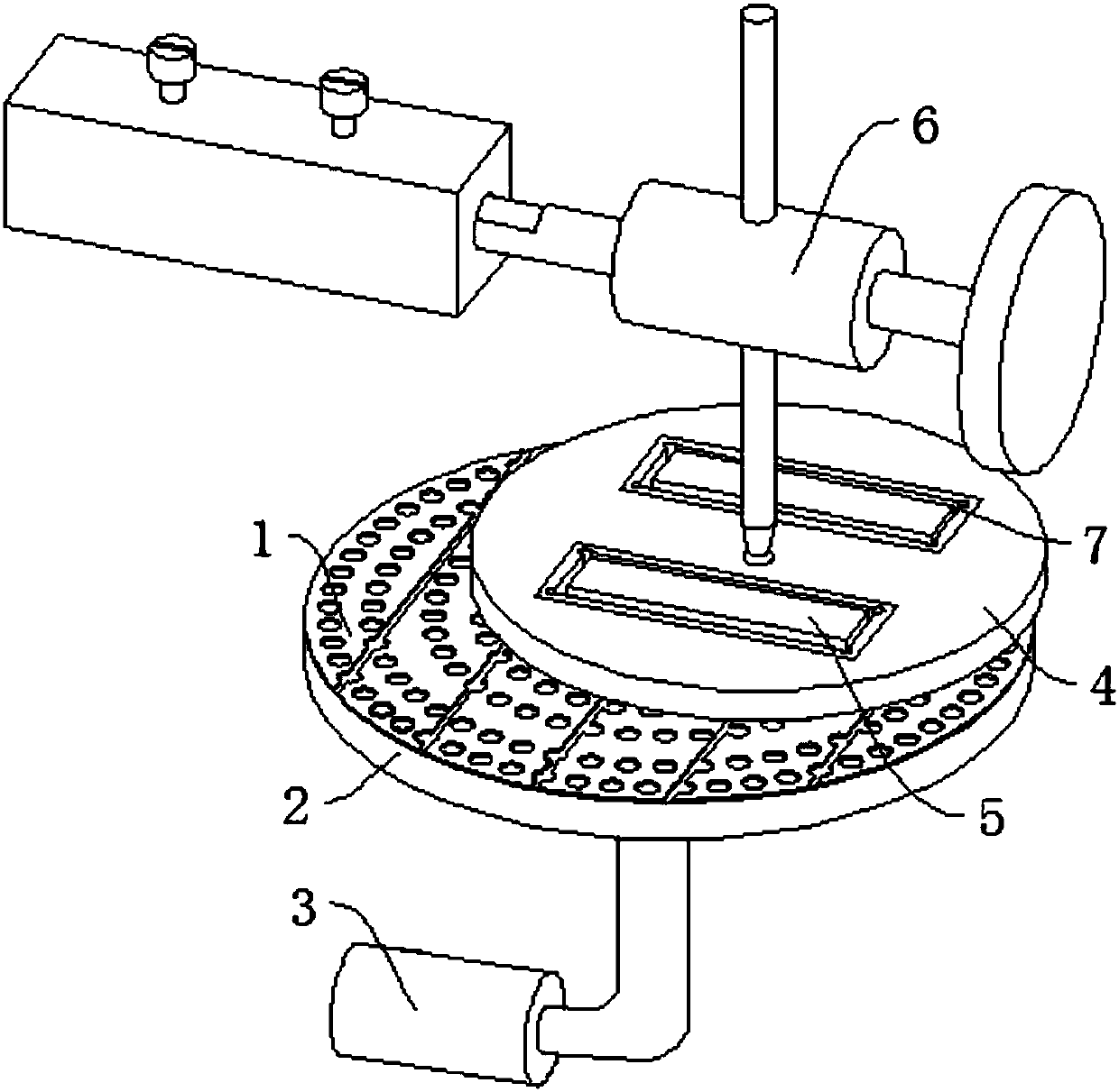
[0031] Referring to the accompanying drawings, in one embodiment of the present invention: an optical lens polishing device includes: a polishing pad 1 , a polishing pad base 2 , a rotary drive device 3 , a separator 4 , a pressing block 5 and a polishing machine 6 . The polishing pad 1 is made of polyurethane, bonded to the polishing pad base 2 by a thermosetting adhesive such as epoxy resin or organic silicon, and the polishing pad base 2 moves under the drive of the rotary drive device 3, which can be an ordinary motor. The separator 4 is placed on the polishing pad 1, the separator 4 is provided with a plurality of loading tanks 7, the loading tanks 7 can be in any shape such as square or circular, and the inner wall of the loading tank 7 is provided with a protective cover; The block 5 is movably placed in the loading tank of the separator 4, and is applied to the lens by the gravity of the pressing block 5 itself; The polishing pad base 2 and the polishing machine 6 form...


PUM

PropertyMeasurementUnit
particle sizeaaaaaaaaaa

Abstract

The invention discloses an optical lens polishing device, comprising: a polishing pad, a polishing pad base, a rotary driving device, a separator, a pressing block and a polishing machine; the polishing pad is arranged on the polishing pad base, and the polishing pad base is connected to the rotary driving device Above; the separator is arranged on the polishing pad, and the separator is provided with a plurality of loading tanks, and the pressing block is arranged in the loading tanks of the separator; a hole is arranged in the middle of the separator, and the separator is connected to the polishing machine through the hole. A polishing process is also disclosed, and the specific steps are as follows: trimming the correction mold; trimming the polishing pad with the correction mold; cleaning the polishing pad; fixing the polishing pad on the base of the polishing pad; preparing the polishing liquid; The polishing liquid circulates in the cylinder; the lens is placed in the load tank of the separator; the pressing block is placed on the lens; the polishing machine and the rotary drive device are started for polishing. Through the above method, the present invention can ensure that the processing surface of the product is on the same plane, the force is uniform, and the polishing effect is improved.

Description

technical field [0001] The invention relates to the technical field of lens processing, in particular to an optical lens polishing device and a polishing process. Background technique [0002] Since the ultra-thin laser optical lens is very easy to deform, in the process of optical processing, the surface shape of the lens is often changed due to thermal changes or uneven force. [0003] The traditional optical lens polishing process is to bond the lens to the chassis with an adhesive, and then put the chassis on the polishing mold for polishing. After polishing, the adhesive is melted by heating, and the lens is removed after the adhesive is completely melted. Lens polishing. [0004] The disadvantage of the traditional optical lens polishing process is that the operation is cumbersome and the efficiency is low. Due to the different conditions of the upper and lower plates, the lens is easily deformed due to elastic deformation during the process of the upper and lower pla...

Claims


Application Information

Patent Timeline
Patent Type & Authority Applications(China)
IPC IPC(8): B24B1/00B24B13/00
CPCB24B1/00B24B13/00
Inventor 周志凯陈锐
Owner II VI OPTICS (SUZHOU) CO LTD
Why Eureka
Try Eureka