Magnetic suspension linear motion platform based on combination of permanent magnets and electromagnets

A linear motion, combined technology, applied in the direction of holding devices, electrical components, etc. using magnetic attraction or thrust, can solve problems such as unfavorable performance and quality of integrated circuit chips, metal dust generated by friction and wear, and low air bearing capacity. , to achieve the effect of low impact resistance and anti-interference ability, reducing mechanical loss, simple and convenient control

Inactive Publication Date: 2012-01-04
CENT SOUTH UNIV
View PDF5 Cites 34 Cited by
  • Summary
  • Abstract
  • Description
  • Claims
  • Application Information

AI Technical Summary

Problems solved by technology

This type of platform mostly adopts traditional solutions such as rotary servo motor drive, precision ball screw drive and mechanical rigid contact method supported by sliding guide rails. This method has friction and wear, produces metal dust, and requires lubrication. ) speed, reversing and parking, the elastic deformation, friction, connection gap and backlash generated by the intermediate link will cause the lag and nonlinear error of the feed movement, and various connection gaps affect the positioning accuracy
The emergence of linear motors overcomes the shortcomings of the rotary motor plus screw drive mode, greatly improving its feed performance, but the metal dust generated by friction is still not conducive to the improvement of the performance and quality of integrated circuit chips
Although the air-floating support method studied in recent years has eliminated friction, because the air-floating platform uses the control of air to accelerate the flow through the air nozzle, it will generate an impact force on the guide rail, so the impact resistance is low, and the air-floating platform is limited to air flow relative to In a small space, when the external air flow is large, it will have a certain impact on its movement. In addition, the air bearing capacity is low, the support stiffness is small, and it is not suitable for working in a vacuum environment, so its advantages are greatly reduced.

Method used


Image

  • Magnetic suspension linear motion platform based on combination of permanent magnets and electromagnets
  • Magnetic suspension linear motion platform based on combination of permanent magnets and electromagnets
  • Magnetic suspension linear motion platform based on combination of permanent magnets and electromagnets

Examples


Embodiment Construction

[0029] The present invention will be further described in detail in conjunction with the accompanying drawings and specific implementation process.

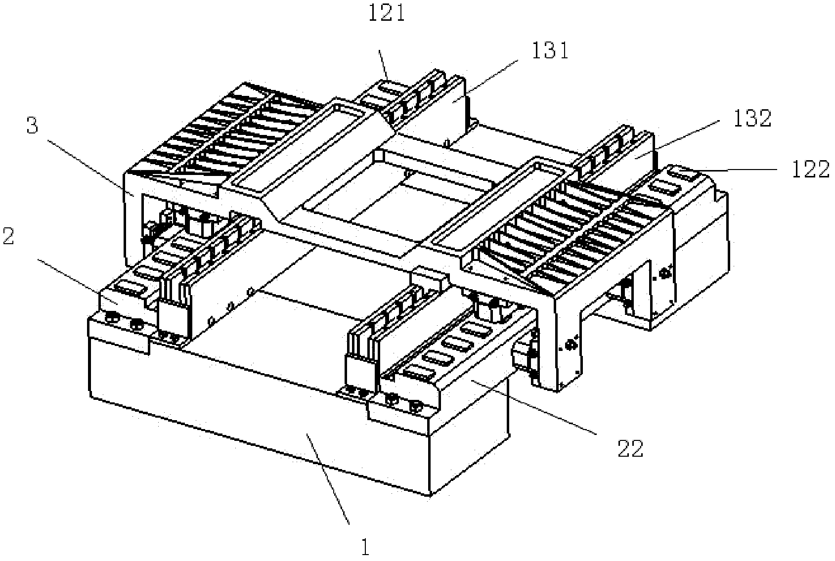
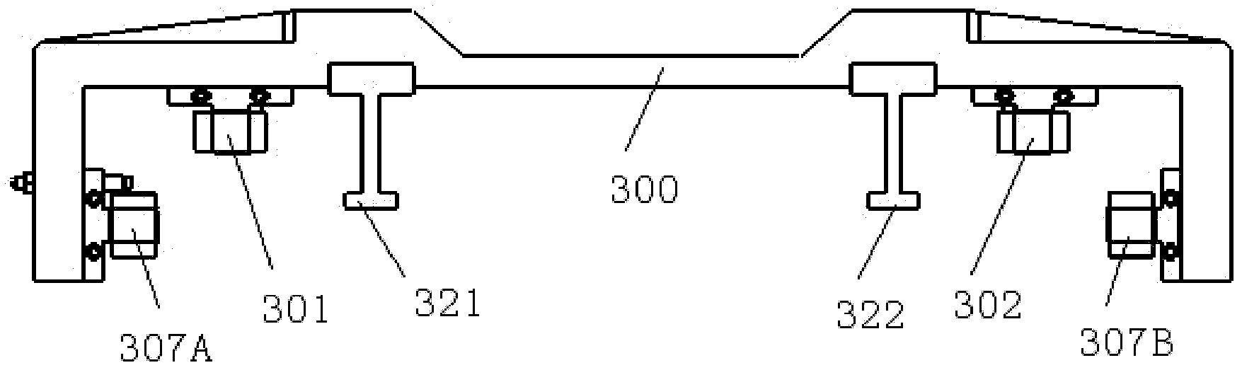
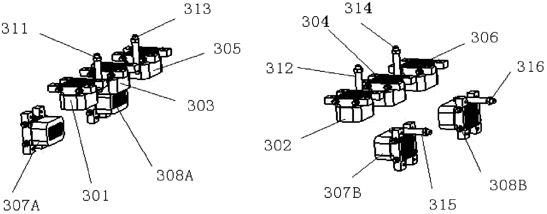
[0030] see figure 1 , figure 2 , image 3 , Figure 4 , Figure 5 and Image 6 , from bottom to top by the granite foundation 1, the first linear guide 2, the second linear guide 22, suspension body 3 three parts. The guide rail surfaces of the first linear guide rail 2 and the second linear guide rail 22 corresponding to the electromagnet are all polished and homogenized, so that the flatness and verticality of the processed guide rail surface can reach micron-level precision. The guide rail surface of the first linear guide 2 is provided with the first permanent magnet 121 of array, the guide rail surface of the second linear guide 22 is provided with the second permanent magnet 122 of array, and the part structure of suspension body 3 is as follows figure 2As shown, there are mainly aluminum alloy U-shaped components 3...


PUM


Abstract

The invention discloses a magnetic suspension linear motion platform based on the combination of permanent magnets and electromagnets. The electromagnets are vertically installed in a suspensoid, array permanent magnets are arranged on the surface of a guide rail, the suspension of the suspensoid can be realized by utilizing the principle of holopolarity repulsion between the electromagnets and the permanent magnets; and meanwhile, an eddy current displacement sensor is combined to realize the stable suspension of the suspensoid above the guide rail; two pairs of electromagnets are horizontally installed in the suspensoid, which can provide guidance for the linear motion of the platform by combining with the eddy current displacement sensor; a linear motor stator is fixed on a base, a linear motor rotor is fixed on the suspensoid, a grating ruler is arranged on the surface of the guide rail, and the reading head of the grating ruler is installed on the suspensoid, thus the precise linear positioning motion of the suspensoid can be realized. The platform provided by the invention can realize the functions such as super cleaning, high speed, long stroke, precise positioning motion and the like, which can not be realized by the traditional scheme that a rotary servo motor is utilized to drive, a precise ball screw is utilized to transmit and a slide guide is utilized to support, and has the advantages of good load bearing characteristic and stable suspension performance.

Description

technical field [0001] The present invention relates to a linear motion platform, in particular to a magnetic levitation linear motion platform combined with permanent magnet and electromagnetic. The magnetic levitation linear motion platform can be applied to high-speed, ultra-clean, In the ultra-precise positioning motion platform. technical background [0002] Modern manufacturing technology is developing in the direction of high speed, precision and modularization. High-tech manufacturing industries such as information not only put forward higher and higher requirements for the performance of processing equipment such as positioning accuracy and speed, but also put forward higher requirements for the production environment. Microelectronic products such as optoelectronic devices and semiconductor chips are required to be processed in an ultra-clean environment. In microelectronic packaging equipment such as eutectic die bonder, automatic gold wire ball bonder and IC chi...

Claims


Application Information

Patent Timeline
Patent Type & Authority Applications(China)
IPC IPC(8): H02N15/00
Inventor 周海波段吉安瞿田华郑蕾王文祝
Owner CENT SOUTH UNIV
Why Eureka
Try Eureka