
Balance transmission system

A transmission system and balancing technology, applied in the direction of transmission, belt/chain/gear, mechanical equipment, etc., can solve the problems of complex structure, narrow application range and high cost of automatic transmission

Pending Publication Date: 2018-02-09
BEIJING JIAJI RUIHUA TECH TRADE
View PDF10 Cites 1 Cited by
  • Summary
  • Abstract
  • Description
  • Claims
  • Application Information

AI Technical Summary

Problems solved by technology

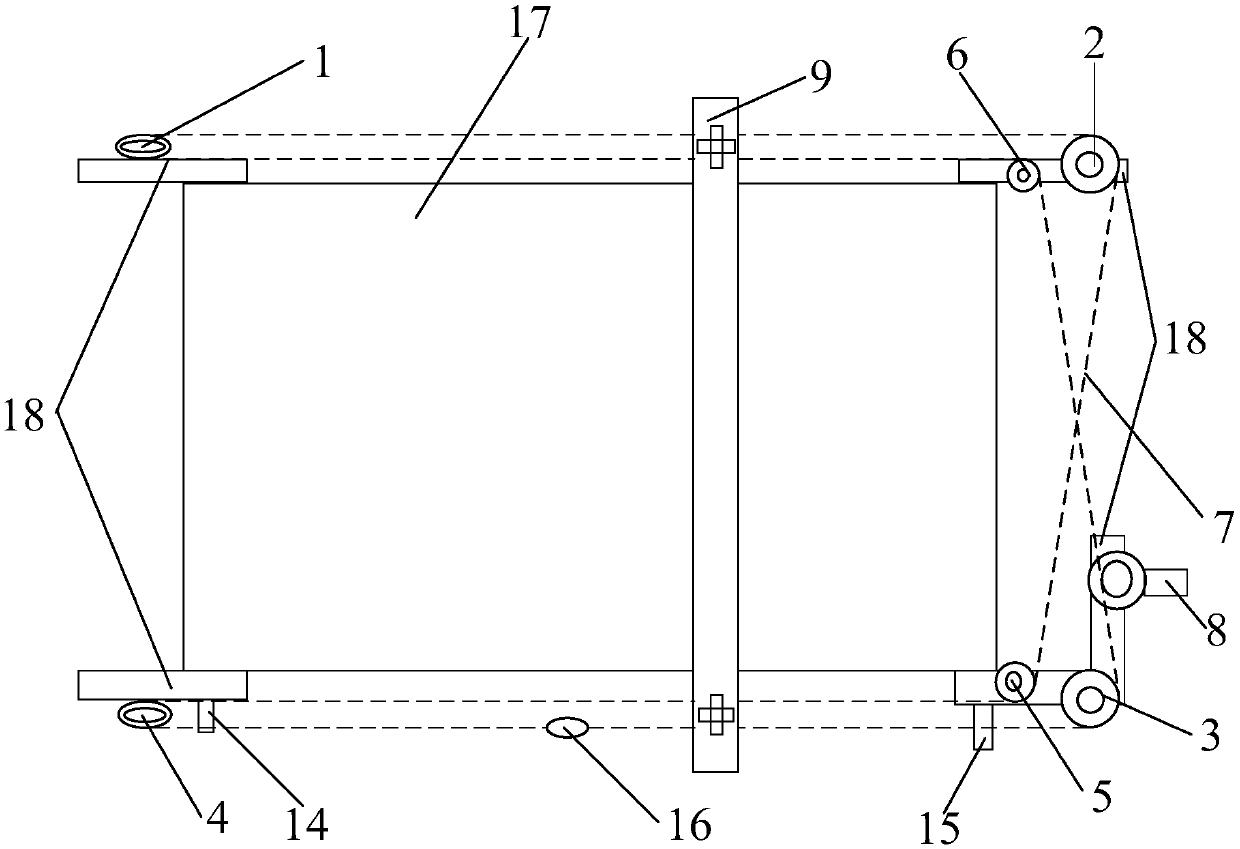
[0004] The purpose of the present invention is to provide a balanced transmission system with high reliability and low cost to solve the problems of complex structure, narrow application range and high cost of the automatic transmission device in the prior art

Method used


Image

  • Balance transmission system
  • Balance transmission system
  • Balance transmission system

Examples


Embodiment Construction

[0025] The technical solutions of the present invention will be clearly and completely described below in conjunction with the accompanying drawings. Apparently, the described embodiments are some of the embodiments of the present invention, but not all of them. Based on the embodiments of the present invention, all other embodiments obtained by persons of ordinary skill in the art without making creative efforts belong to the protection scope of the present invention.

[0026] In the description of the present invention, it should be noted that the terms "center", "upper", "lower", "left", "right", "vertical", "horizontal", "inner", "outer" etc. The indicated orientation or positional relationship is based on the orientation or positional relationship shown in the drawings, and is only for the convenience of describing the present invention and simplifying the description, rather than indicating or implying that the referred device or element must have a specific orientation, ...


PUM


Abstract

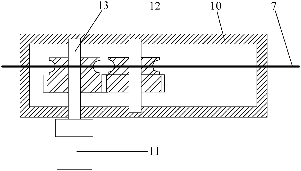
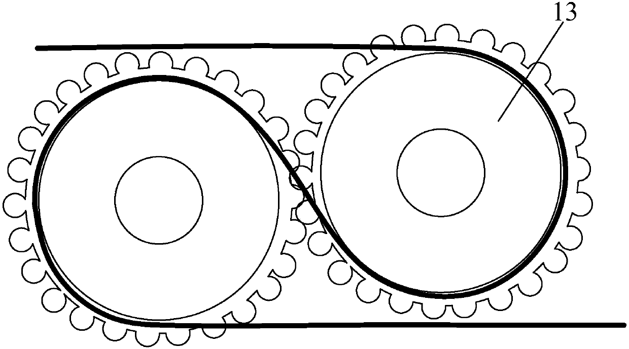
The invention discloses a balance transmission system. The balance transmission system comprises a pulley, ropes and a transmission device; a transmission system is formed through steering and slidingeffects of the pulley; two sections of ropes with the same motion directions in the transmission system are adopted to replace slide rails to provide positioning installation to a strip module; and the strip module is driven to move on a frame by the transmission device to realize work of the strip module. The transmission device solves the balance problem during moving under the condition of notdepending on such additional parts as the slide rails, realizes organic unity of transmission and balance, and can effectively reduce the cost when improving the system stability and reliability.

Description

technical field [0001] The invention belongs to the technical field of a balanced transmission system, in particular to a balanced transmission system. Background technique [0002] Reciprocating motion is widely used in current mechanical equipment. Most of the functions need to be realized by driving certain components through the transmission system through reciprocating motion, such as scanners, cleaning brushes and so on. But these transmission systems are all realized by a pair of guide rails set correspondingly and slide blocks installed thereon. However, the guide rail transmission has the following defects: firstly, due to the limitation of the use scene, most of the guide rails are straight structures, which can only drive the sliding structure to move on the flat surface and cannot be used for curved surface structures; secondly, most of the guide rails are made of metal with high strength. The material is used to ensure strength and prevent wear, so most of them...

Claims


Application Information

Patent Timeline
Patent Type & Authority Applications(China)
IPC IPC(8): F16H37/12
CPCF16H37/12
Inventor 马文生
Owner BEIJING JIAJI RUIHUA TECH TRADE
Learn More