
A full-sea deep ultra-high pressure seawater speed regulating valve

A speed regulating valve, ultra-high pressure technology, applied in the direction of safety valve, balance valve, valve device, etc., can solve the problems of aggravated valve core vibration, increased valve port flow rate, valve port erosion, etc., to reduce valve port impact Corrosion, prevent spool sticking, and reduce vibration

Active Publication Date: 2018-11-30
HUAZHONG UNIV OF SCI & TECH
View PDF5 Cites 0 Cited by
  • Summary
  • Abstract
  • Description
  • Claims
  • Application Information

AI Technical Summary

Problems solved by technology

[0003] However, if in deep sea conditions, such as the inlet of the speed regulating valve is connected to seawater, and the outlet of the speed regulating valve is connected to a pressure-resistant water tank (the internal pressure is much lower than the pressure of the deep sea environment), at this time, under the action of the huge pressure difference in the deep sea, the conventional speed regulating valve will reduce the pressure. The opening of the pressure port will be small, and the pressure reducing port will be in the state of either opening or closing, which will aggravate the vibration of the valve core; Cause valve port erosion and serious cavitation

Method used


Image

  • A full-sea deep ultra-high pressure seawater speed regulating valve
  • A full-sea deep ultra-high pressure seawater speed regulating valve
  • A full-sea deep ultra-high pressure seawater speed regulating valve

Examples


Embodiment Construction

[0024] In order to make the object, technical solution and advantages of the present invention clearer, the present invention will be further described in detail below in conjunction with the accompanying drawings and embodiments. It should be understood that the specific embodiments described here are only used to explain the present invention, not to limit the present invention. In addition, the technical features involved in the various embodiments of the present invention described below can be combined with each other as long as they do not constitute a conflict with each other.

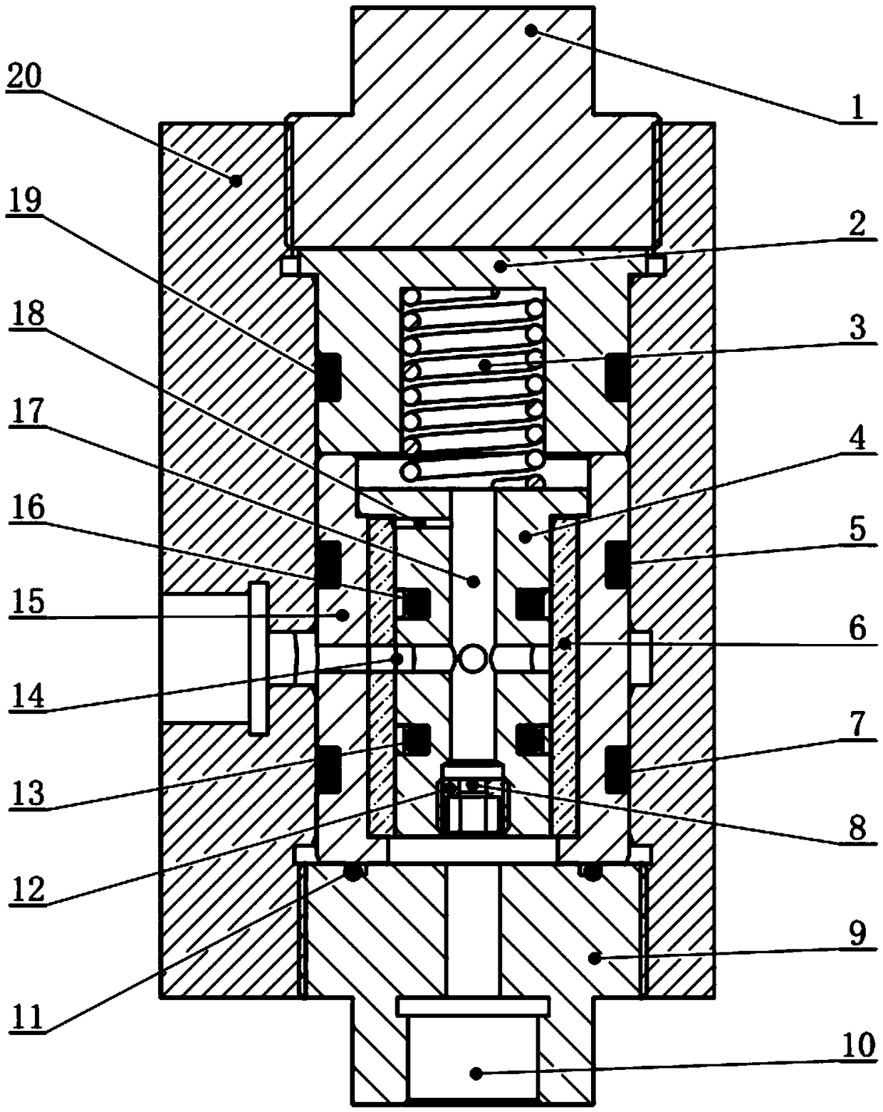
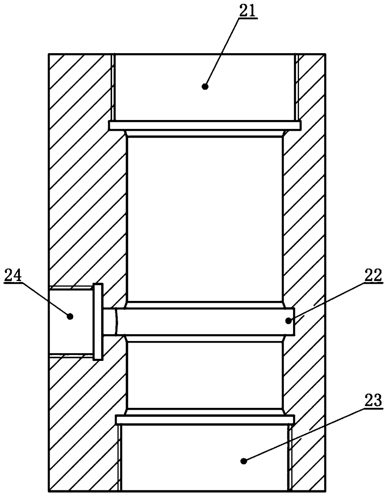
[0025] Such as figure 1 As shown, a full-sea deep ultra-high pressure seawater speed regulating valve provided by the embodiment of the present invention includes a valve body 20, a valve sleeve assembly and a valve core assembly, wherein the valve body 20 is a hollow structure, and a speed regulating valve is provided on it. The valve outlet 24 and the valve sleeve assembly are installed in th...


PUM


Abstract

The invention belongs to the field of valves and discloses a full-sea-depth and extrahigh-pressure seawater speed regulating valve. The whole-sea-depth and extrahigh-pressure seawater speed regulatingvalve comprises a valve body, a valve sleeve assembly and a valve element assembly, wherein a speed regulating valve outlet is formed in the valve body; the valve sleeve assembly comprises a locatingplug, a spring cover, a valve sleeve and a pressing plug, the locating plug is connected with the upper end of the valve body, a ceramic sleeve is embedded in the valve sleeve, a first runner is formed in the side surfaces of the valve sleeve and the ceramic sleeve, and a speed regulating valve inlet is formed in the pressing plug; and the valve element assembly comprises a valve element mountedin the ceramic sleeve, a guiding channel is formed in the valve element, the guiding channel communicates with the first runner through a second runner, an arch-shaped pressure reducing opening is formed in the communicating part, the upper end of the valve element is in contact with a spring, a throttling valve plug is arranged in the lower part of the valve element, and a throttling opening usedfor communicating the speed regulating valve inlet and the guiding channel is formed in the throttling valve plug. The whole-sea-depth and extrahigh-pressure seawater speed regulating valve has the characteristics of large working pressure difference range, small vibration and valve opening erosion resistance and the like, and can realize effective and reliable control over the flow of a hydraulic system in a sea area at any depth.

Description

technical field [0001] The invention belongs to the field of valves, and more specifically relates to a full-sea deep ultra-high pressure seawater speed regulating valve, which can be applied to flow control of water hydraulic systems in deep-sea equipment. Background technique [0002] The speed control valve, also known as the flow valve, is a type of valve used in the hydraulic system to control the flow of the system. The speed regulating valve is generally composed of a throttle valve and a pressure reducing valve in series. By adjusting the opening of the pressure reducing valve, the pressure difference between the two ends of the throttle valve is kept constant, so as to ensure that the flow through the speed regulating valve remains constant. At present, the speed regulating valves on the market all use the combination of the above-mentioned throttle valve and pressure reducing valve. [0003] However, if in deep sea conditions, such as the inlet of the speed regula...

Claims


Application Information

Patent Timeline
Patent Type & Authority Patents(China)
IPC IPC(8): F16K17/30F16K17/34F16K3/26F16K3/314F16K47/00
CPCF16K3/243F16K3/262F16K3/314F16K17/30F16K17/34F16K47/00
Inventor 李超吴德发刘银水程谦邓亦攀庞浩翟小敏王乐
Owner HUAZHONG UNIV OF SCI & TECH
Learn More