Coaxial microstrip transition device

A microstrip and coaxial technology, applied in connection devices, electrical components, circuits, etc., can solve the problems of poor high-frequency performance, poor process consistency, and low energy conversion efficiency, achieving good consistency, good microwave signal matching, Conducive to the effect of microwave signal transmission

Inactive Publication Date: 2018-02-09
BEIJING INST OF REMOTE SENSING EQUIP
View PDF6 Cites 2 Cited by
  • Summary
  • Abstract
  • Description
  • Claims
  • Application Information

AI Technical Summary

Problems solved by technology

[0003] The purpose of the present invention is to provide a coaxial microstrip conversion device to solve the problems of poor hig

Method used


Image

  • Coaxial microstrip transition device
  • Coaxial microstrip transition device
  • Coaxial microstrip transition device

Examples


Example Embodiment

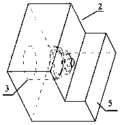
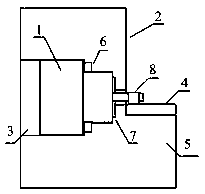
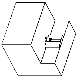
[0014] A coaxial microstrip conversion device includes a coaxial connector 1 and a box body 2, and also includes a solder ring 6, a cavity matching groove 7 and a gold ribbon ring 8.

[0015] The input and output of the radio frequency component are connected with the external signal through the coaxial connector 1. The input and output positions of the radio frequency component box 2 are equipped with a coaxial connector mounting hole 3, a cavity matching groove 7 and a solder ring 6. The mounting hole position is for the radio frequency component input At the output, the shape of the mounting hole matches the coaxial connector 1 used; the cavity matching groove 7 is a ring concentric with the coaxial mounting hole; the solder ring 6 is the position directly above the coaxial connector mounting hole 3 on the box body 2, and the shape is Same as the coaxial connector mounting hole 3, 1mm larger than the coaxial connector mounting hole 3. A microstrip substrate mounting surface 5 ...


PUM


Abstract

The present invention discloses a coaxial microstrip transition device. The device comprises a coaxial joint and a box body (2), and also comprises a solder ring, a cavity matching groove and a metalstrip ring. The solder ring makes sealing and consistence of welding of the coaxial joint better, and make grounding of microwave signals better; the welding technology mode of the metal strip ring ensures batch consistence of performances of a transition device and performs interaction with the cavity matching groove, and the matching of the microwave signals is better to achieve high-efficiencyenergy transition. After the coaxial joint is fixed on the box body through a coaxial joint installation hole (3), and the coaxial joint is welded with the box body through the solder ring so that thesealing of the combination is ensured and the coaxial joint and the housing is better connected to facilitate transmission of the microwave signals.

Description

technical field [0001] The invention relates to a microstrip conversion device, in particular to a coaxial microstrip conversion device. Background technique [0002] For highly integrated RF components, the external interface is generally in the form of coaxial SMA, SMP, etc., and the components are all RF components and chips in the form of microstrip, so the coaxial microstrip conversion device is an essential component of RF components part. In the past, coaxial connectors in the form of SMA, SMP, etc. were usually used, fixed or welded on the box body with screws, and then the inner conductor was directly welded on the microstrip substrate, and the external RF input signal was connected to the input end of the RF component through the coaxial connector. The output end of the radio frequency component is used as the output end of the radio frequency component after passing through the coaxial connector. The high-frequency performance of this method is poor, the energy ...

Claims


Application Information

Patent Timeline
IPC IPC(8): H01P5/08
CPCH01P5/085
Inventor 丁红旗
Owner BEIJING INST OF REMOTE SENSING EQUIP
Why Eureka
Try Eureka