
Power transmission line deicing device propelled along spiral trajectory

A technology for transmission lines and transmission lines, which is applied in the installation of cables, overhead installation, electrical components, etc. It can solve problems such as short circuit, insulator string inclination, and difficulty in achieving the expected effect, and achieve the effect of avoiding damage and simple device structure

Active Publication Date: 2018-02-09
STATE GRID HEBEI ELECTRIC POWER CO LTD +1
View PDF6 Cites 3 Cited by
  • Summary
  • Abstract
  • Description
  • Claims
  • Application Information

AI Technical Summary

Problems solved by technology

For lines with vertically arranged conductors, when the ice coating on the lower conductors falls off first (the ice coating on the conductors does not necessarily fall off at the same time), the conductors will rise rapidly or jump up and down, causing a phase-to-phase short circuit, causing the line switch to trip and power supply to interrupt
[0005] (3) The insulator string is inclined and the wire is seriously drooping
In the span where the ice is too thick, it will cause the wire to droop seriously and cause a grounding accident
[0006] (4) After the insulator string is covered with ice, the insulation performance will be greatly reduced
When the hanging insulator string is covered with ice and melts, icicles may be formed, short-circuiting the insulator string and causing a grounding accident
[0007] At present, there are mainly two types of risk removal methods: ice melting and mechanical deicing. Among them, the ice melting method is to heat the transmission line to achieve ice melting. heat generation), short-circuit ice melting (suitable for three-phase power transmission lines), high-frequency excitation ice melting (using the skin effect of high-frequency high-voltage electricity to cause resistance loss and heat on the transmission line to melt ice), using The deicing method inevitably requires a certain degree of transformation of the transmission line, and requires a large amount of energy for heating, and the cost and difficulty of deicing are high; while mechanical deicing is mainly carried out by equipment installed on the transmission line. The main method is to use knocking, shaking or blasting. The problem is that the area where the transmission line is located is generally strong wind, and the equipment is deflected by the wind, making it difficult to work effectively. The thicker ice layer on the transmission line is crushed, which makes the deicing work less effective and difficult to achieve the expected effect. The blasting method needs to fix the blasting body on the ice layer in advance, and the blasting method is external blasting, which has limited deicing effect and low efficiency.

Method used


Image

  • Power transmission line deicing device propelled along spiral trajectory
  • Power transmission line deicing device propelled along spiral trajectory
  • Power transmission line deicing device propelled along spiral trajectory

Examples


specific Embodiment 1

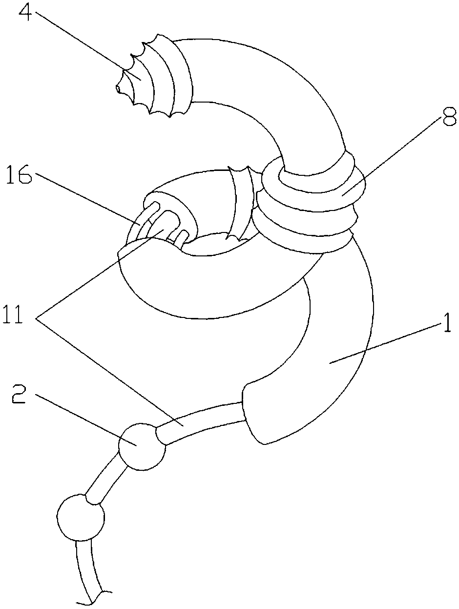
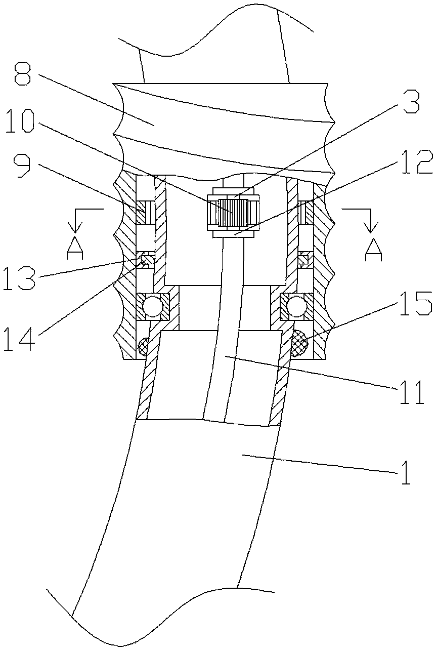
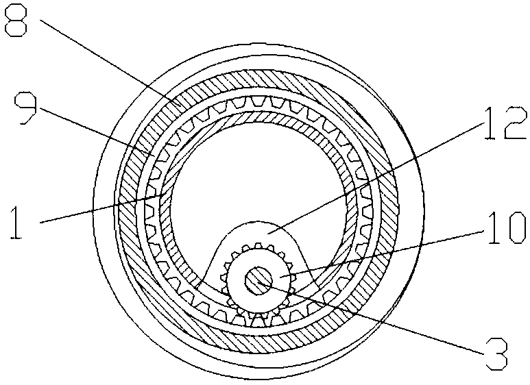
[0028] Specific embodiment 1, such as Figure 1 to Figure 4 As shown, the present invention is a power transmission line deicing device propelled along a spiral trajectory, which is used to remove the ice layer around the power transmission line. The device includes a device body 1, a blasting body 2 arranged at the tail of the device body 1, and the device The main body 1 is helical, and the head of the device main body 1 is also provided with a drill bit 4, and the device main body 1 has the degree of freedom to rotate around the axis of the transmission line by means of the drill bit 4 and the driving mechanism. The present invention is driven by the transmission shaft 3 during work, and the section of the ice layer is cleaned out by personnel on the ice-coated transmission line before use, and then the deicing device of the present invention is wound and arranged on the cleaned-up transmission line, and the drill bit is used to remove the ice. Holes are drilled in the ice-...

specific Embodiment 2

[0031] Specific embodiment 2, described drill bit comprises the drill bit 4 that is the conical structure that is connected with transmission shaft 3, is arranged on the connection structure between drill bit 4 and device body 1, and drill bit 4 has around device body 1 by means of this connection structure. The degree of freedom of axis rotation, the connection structure includes a locking ring 5 fixed to the bottom of the drill bit 4, a positioning ring 6 is clamped between the locking ring 5 and the bottom surface of the drill bit 4, and the positioning ring 6 is set Fixed on the outer wall of the device body 1, the positioning ring 6 forms rolling contact with the bottom surface of the drill bit 4 and the ring surface of the locking ring 5 by means of balls 7 respectively. The transmission shaft 3 drives the drill bit 4 to work. When the drill bit 4 advances with the device body 1, the rolling connection of the balls on the positioning ring 6 reduces the resistance and faci...


PUM


Abstract

The invention relates to a power transmission line deicing device propelled along a spiral trajectory, and belongs to the field of power transmission line deicing and maintenance equipment, and the driving device body is driven by a drill bit and a driving mechanism to be inserted into the ice coating layer, an ice layer is broken by the aid of a blasting body dragged on the rear side of the device body, and the deicing effect is guaranteed. The spiral device body is wound on the power transmission line, so that the running track is spiral, the device is simple in structure, the drill bit andthe driving mechanism in the device are mechanically driven, damage caused by explosion due to an electrical element is avoided, and the safety and stability of equipment are guaranteed.

Description

technical field [0001] The invention belongs to the field of power transmission line deicing maintenance equipment, and in particular relates to a power transmission line deicing device propelled along a spiral track. Background technique [0002] Transmission lines are usually erected in an open field environment. When the ambient temperature drops in winter, the moisture in the air will condense on the transmission line to form icing, and the icing of transmission lines will cause the following hazards: [0003] (1) Damage to the tower. If the line is covered with ice too thick, the mechanical load of the tower will be overloaded and broken. [0004] (2) Line tripping. For lines with vertically arranged conductors, when the ice coating on the lower conductors falls off first (the ice coating on the conductors does not necessarily fall off at the same time), the conductors will rise rapidly or jump up and down, causing a phase-to-phase short circuit, causing the line swit...

Claims


Application Information

Patent Timeline
Patent Type & Authority Applications(China)
IPC IPC(8): H02G7/16
CPCH02G7/16
Inventor 张磐王克海刘立强刘辉安英娟周兆辉赵洪波孟霖安琳婷师进冲何佳晟
Owner STATE GRID HEBEI ELECTRIC POWER CO LTD
Learn More