
An active and passive limb rehabilitation trainer

An active-passive, trainer technology, applied in the direction of muscle training equipment, passive exercise equipment, gymnastics equipment, etc., can solve the problems of complex structure, the position of the traction mechanism of the limbs cannot be adjusted, and the rehabilitation training requirements of patients cannot be met.

Inactive Publication Date: 2019-02-22
ANYANG INST OF TECH
View PDF4 Cites 0 Cited by
  • Summary
  • Abstract
  • Description
  • Claims
  • Application Information

AI Technical Summary

Problems solved by technology

However, the current limb rehabilitation training device has a complex structure and high cost, and the position of the active and passive rehabilitation training device's limb traction mechanism cannot be adjusted, which cannot meet the rehabilitation training requirements of some patients. The mechanism is bulky. When the patient actively moves, the force of detecting the movement of the patient's limbs is usually used to drive the motor to rotate through the control system to drive the movement of the patient's limbs. Due to the use of electrical and mechanical structures, the safety is poor

Method used


Image

  • An active and passive limb rehabilitation trainer
  • An active and passive limb rehabilitation trainer
  • An active and passive limb rehabilitation trainer

Examples


Embodiment 1

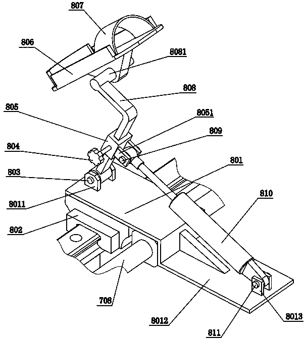
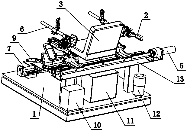
[0056]When the patient needs one side of the upper limb to drive the other side of the upper limb for rehabilitation training, the patient sits on the seat 3. If the patient's right arm can move autonomously, when the patient's left arm needs to be recovered, the servo motor is controlled to rotate at 150° , the reverse threads on both sides of the driving lead screw 1 505 drive the right nut 1 506 and the left nut 1 507 to move towards each other or reversely, and the right connecting plate 702 and the left connecting plate 602 move to realize the left upper limb mechanism 6 and the right upper limb mechanism 2 at the same time Move to the inside or outside of the patient, to adapt to the needs of the patient's shoulder width, the screw thread on the leading screw-505 and the right nut-506, the left nut-507 adopt self-locking screws, such as common triangular threads for connection, to prevent the nut from moving along Lead screw one 505 rotates independently, unscrews the rig...

Embodiment 2

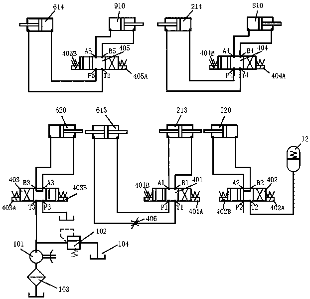
[0058] If control system 4 controls the left side electromagnet 401B of three-position four-way valve one 401 to energize, the left side electromagnet 404B of three-position four-way valve four 404 is energized, the left side electromagnet 405B of three-position four-way valve five 405 is energized, The electromagnets 403A and 403B on both sides of the three-position four-way valve three 403 are energized alternately, while the electromagnets 402A and 402B on both sides of the three-position four-way valve two 402 are not energized, the motor of the hydraulic pump 101 is energized, and the left piston cylinder three 620 The piston rod moves to drive the piston rods of the left double side rod-out piston cylinder 613 and the right oil cylinder one 614 to move, so as to realize the passive movement of the patient's bilateral limbs approximate gait.

Embodiment 3

[0060] If the control system 4 controls the energization of the right electromagnet 401A of the three-position four-way valve one 401, the patient's bilateral upper limbs move downward synchronously, and at the same time controls the power-on of the left electromagnet 404B of the three-position four-way valve four 404, three-position four-way valve four 404 The left electromagnet 405B of the five-way valve 405 is energized, the electromagnets 403A and 403B on both sides of the three-position four-way valve three 403 are not energized, the left electromagnet 402B of the three-position four-way valve two 402 is energized, and the motor of the hydraulic pump 101 Without electricity, the oil inlet A2 of the three-position four-way valve 2 402 is connected to the pressure port P2, the oil outlet B2 is connected to the oil return port T2, the upper limbs on both sides swing downward, and the right piston cylinder 3 220 passes through the three-position four-way valve The air in the o...


PUM


Abstract

The invention provides an active and passive limb rehabilitation training device. The training device comprises a base, a left upper limb mechanism, a right upper limb mechanism, a left lower limb mechanism and a right lower limb mechanism, wherein the left upper limb mechanism and the right upper limb mechanism are installed on the two sides of a double-upper-limb position adjusting mechanism fixed to the base respectively, the left lower limb mechanism and the right lower limb mechanism are installed on the two sides of a double-lower-limb position adjusting mechanism fixed to the base respectively, the two lower limb mechanisms are bilaterally symmetrical, and the two upper limb mechanisms are basically bilaterally symmetrical. A right rotating shaft is rotationally installed on a rightupper limb connecting frame of the right upper limb mechanism and is connected with a piston rod on one side of a right double-side rod outlet oil cylinder and a piston rod of a first right oil cylinder through a gear-rack and guide rail-slider mechanism, a piston rod on the other side of the right double-side rod outlet oil cylinder is connected with a piston rod of a third right oil cylinder, aright connecting plate of the right lower limb mechanism is connected with a second right foot connecting rod and a fourth right coil cylinder in a hinged mode, and a piston rod of the fourth right oil cylinder is connected with a right foot swing rod in a hinged mode. A right double-side rod outlet piston cylinder is connected with a left double-side rod outlet piston cylinder through a three-position four-way valve, the fourth right oil cylinder is connected with the first right oil cylinder through a three-position four-way valve, a fourth left oil cylinder is connected with a first left oil cylinder through a three-position four-way valve, a third right piston cylinder is connected with the atmosphere and an energy accumulator through a three-position four-way valve, and a third leftpiston cylinder is connected with a hydraulic pump and an oil tank through a three-position four-way valve.

Description

technical field [0001] The invention relates to an active and passive limb rehabilitation trainer, which belongs to the field of rehabilitation medical equipment. Background technique [0002] my country has a large population, and the trend of aging is obvious. The number of patients with stroke, hemiplegia, and cerebral apoplexy is increasing year by year. Most patients have motor dysfunction on one side of their limbs. The quality of life of these patients is seriously reduced, and they need family care. Heavy living burden, with the continuous development of traditional Chinese medicine rehabilitation theory, through repeated external stimuli, the patient's damaged brain function can be compensated through brain tissue, providing a high quality of life for the patient, and even realizing the patient's complete self-care in life. However, the current limb rehabilitation training device has a complex structure and high cost, and the position of the active and passive rehabi...

Claims


Application Information

Patent Timeline
Patent Type & Authority Patents(China)
IPC IPC(8): A63B23/12A63B21/008A63B24/00A61H1/02
CPCA61H1/0237A61H1/0274A61H2201/0149A61H2201/1276A61H2201/1409A61H2201/1635A61H2201/164A61H2201/50A61H2205/06A61H2205/10A63B21/00178A63B21/0083A63B23/12A63B24/0087A63B2210/02A63B2225/093
Inventor 王振宁李源国秀丽吴贵军
Owner ANYANG INST OF TECH
Learn More