Fuel storage device

A fuel storage and fuel technology, applied in the direction of the arrangement combined with the fuel supply of internal combustion engines, electrochemical generators, container filling methods, etc., can solve the problems of high weight, expensive fuel storage, and unoptimized storage volume, etc., to achieve small effect of weight

Active Publication Date: 2018-02-13
ROBERT BOSCH GMBH
View PDF19 Cites 1 Cited by
  • Summary
  • Abstract
  • Description
  • Claims
  • Application Information

AI Technical Summary

Problems solved by technology

The disadvantage here is that, on the one hand, relatively expensive (deep-drawn) tools are required for the manufacture of such a fuel reservoir, and moreover, due to the material of the sheet metal (which is not available for storing fuel) around the single volume and connecting lines, the fuel The reservoir has a high weight and the storage volume has not been optimized

Method used


Image

  • Fuel storage device
  • Fuel storage device

Examples


Embodiment Construction

[0018] In the figures, the same elements or elements with the same function are provided with the same reference numerals.

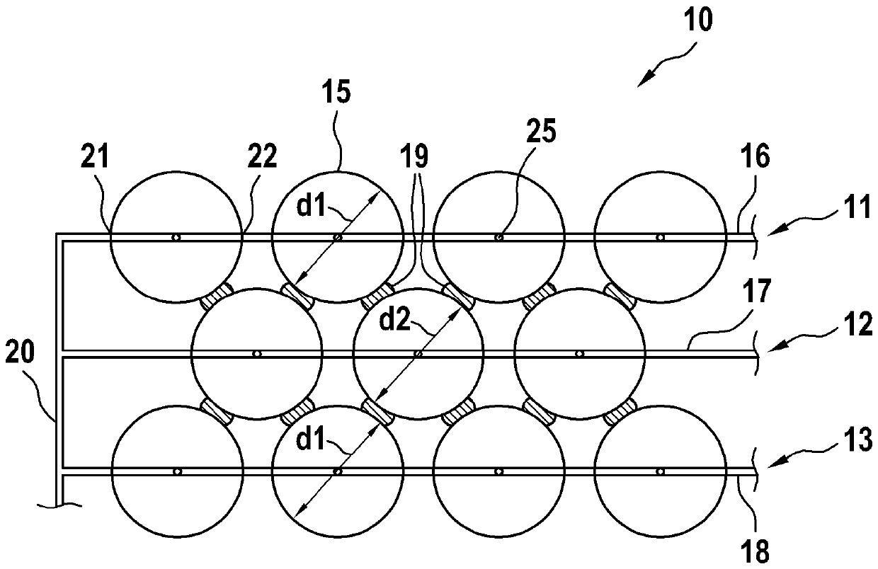
[0019] exist figure 1 The fuel accumulator 10 shown in is used as a storage tank for storing gaseous fuel, for example hydrogen, in a motor vehicle. However, the invention is not restricted to the use of hydrogen as a gaseous fuel and to the use in motor vehicles.

[0020] The fuel storage tank 10 is designed in particular to store gaseous fuel at a pressure between 200 bar and 700 bar. The fuel storage tank 10 has, for example, three layers 11 , 12 and 13 arranged parallel to one another, wherein the layers 11 to 13 each have a plurality of individual volumes 15 designed as hollow spheres for storing gaseous fuel. The single volume 15 of the two outer layers 11 and 13 has, for example, a diameter d 1 , which is slightly larger than the diameter d of the single volume 15 of the intermediate layer 12 2 , wherein the individual volumes 15 of the two ou...


PUM


Abstract

The invention relates to a fuel storage device (10;10a) which is particularly used for a gasous fuel under pressure in a motor vehicle. The fuel storage device is provided with a plurality of spherical single chambers (15) which are interconnected with connecting lines (16,17,18,20,30).

Description

technical field [0001] The invention relates to a fuel accumulator in a motor vehicle, in particular for gaseous fuel under pressure. Background technique [0002] When storing gaseous fuels in motor vehicles, where the fuel pressure is typically between 200 bar and 700 bar, fuel reservoirs made of carbon-fibre-reinforced plastic are generally used. Such fuel accumulators, which are generally always of cylindrical design, have the advantage that they withstand high pressures and thus complete the crash tests required for safety reasons. In addition, they also have a lower weight. A disadvantage of such a fuel tank made of carbon-fibre-reinforced plastic is its relatively high production cost, since its production is relatively expensive and generally cannot be automated or only a small part can be automated. [0003] A fuel reservoir according to the invention is thus known from DE 102 59 204 A1, which has spherical individual volumes which are connected to one another by ...

Claims


Application Information

Patent Timeline
Patent Type & Authority Applications(China)
IPC IPC(8): B60K15/073B60K15/03
CPCB60K15/03006B60K15/073B60K2015/03144F17C13/08F17C2201/0128F17C2201/0166F17C2201/0171F17C2201/056F17C2203/015F17C2203/0639F17C2205/0142F17C2209/2181F17C2209/221F17C2221/012F17C2223/0123F17C2223/036F17C2260/018F17C2270/0168F17C2201/0157F17C2260/011F17C2260/012F17C2270/0184Y02E60/32
Inventor K.韦贝尔
Owner ROBERT BOSCH GMBH
Why Eureka
Try Eureka