

Special cable winding equipment
A technology for equipment and cables, applied in the field of special cable winding equipment, can solve the problems of high labor intensity, time-consuming and laborious manual winding of cables, slow winding speed, etc.
- Summary
- Abstract
- Description
- Claims
- Application Information
AI Technical Summary
Problems solved by technology
Method used
Image

Examples
Embodiment 1
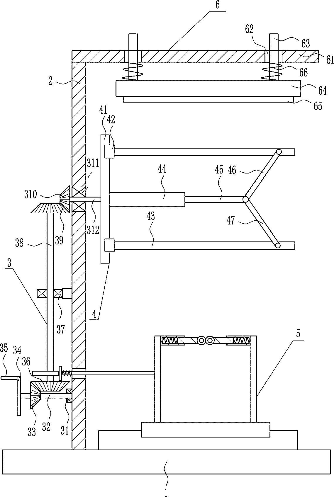
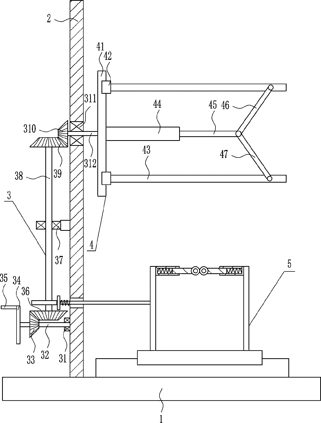
[0038] A special winding equipment for cables, such as Figure 1-8 As shown, it includes a base plate 1, a bracket 2, a rotating device 3 and a fixing device 4. The left side of the top of the base plate 1 is connected with a bracket 2 by means of bolt connection, and the left side of the bracket 2 is provided with a rotating device 3. The rotation of the rotating device 3 A fixing device 4 is arranged on the component, and the fixing device 4 is located on the right side of the bracket 2 .
Embodiment 2
[0040] A special winding equipment for cables, such as Figure 1-8 As shown, it includes a base plate 1, a bracket 2, a rotating device 3 and a fixing device 4. The left side of the top of the base plate 1 is connected with a bracket 2 by means of bolt connection, and the left side of the bracket 2 is provided with a rotating device 3. The rotation of the rotating device 3 A fixing device 4 is arranged on the component, and the fixing device 4 is located on the right side of the bracket 2 .
[0041] The rotating device 3 includes a first bearing seat 31, a first rotating shaft 32, a first bevel gear 33, a turntable 34, a handle 35, a second bevel gear 36, a second bearing seat 37, a second rotating shaft 38, and a third bevel gear 39 , the fourth bevel gear 310, the third bearing seat 311 and the third rotating shaft 312, the lower part of the left side of the bracket 2 is installed with the first bearing seat 31 by bolt connection, and the bearings in the first bearing seat 3...
Embodiment 3
[0043] A special winding equipment for cables, such as Figure 1-8 As shown, it includes a base plate 1, a bracket 2, a rotating device 3 and a fixing device 4. The left side of the top of the base plate 1 is connected with a bracket 2 by means of bolt connection, and the left side of the bracket 2 is provided with a rotating device 3. The rotation of the rotating device 3 A fixing device 4 is arranged on the component, and the fixing device 4 is located on the right side of the bracket 2 .
[0044] The rotating device 3 includes a first bearing seat 31, a first rotating shaft 32, a first bevel gear 33, a turntable 34, a handle 35, a second bevel gear 36, a second bearing seat 37, a second rotating shaft 38, and a third bevel gear 39 , the fourth bevel gear 310, the third bearing seat 311 and the third rotating shaft 312, the lower part of the left side of the bracket 2 is installed with the first bearing seat 31 by bolt connection, and the bearings in the first bearing seat 3...
PUM
 Abstract
Description
Claims
Application Information