Steak beating device

A steak and sliding device technology, applied in slaughtering, meat tenderization, food science and other directions, can solve the problems of uneven fiber, uniform surface force, low hammering efficiency, etc., and achieve uniform hammering, fast frequency, and high hammering efficiency. Effect

Active Publication Date: 2018-02-16
唐山市施尔得肉制品有限公司
View PDF6 Cites 5 Cited by
  • Summary
  • Abstract
  • Description
  • Claims
  • Application Information

AI Technical Summary

Problems solved by technology

But this kind of equipment can't make the surface of the meat uniform,

Method used


Image

  • Steak beating device
  • Steak beating device
  • Steak beating device

Examples


Example Embodiment

Specific implementation manner two:

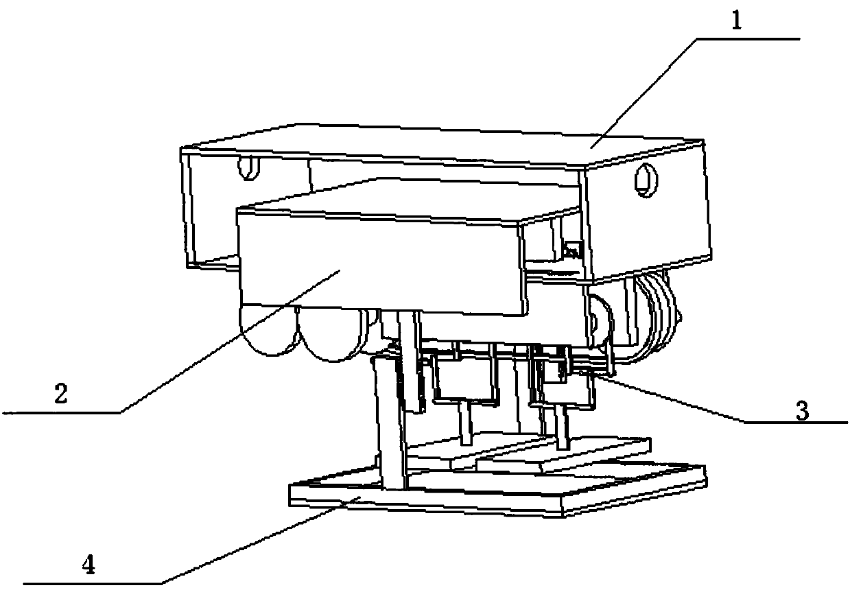
[0032] Such as figure 1 , figure 2 , image 3 , Figure 4 , Figure 5 , Image 6 , Figure 7 , Figure 8 , Picture 9 , Picture 10 with Picture 11 As shown, a steak beating device includes a main board block 1, a sliding device 2, an operating mechanism 3, and a holding plate 4. The sliding device 2 is slidably connected to the main board block 1, and the operating mechanism 3 is fixedly connected to the main board block 1. The sliding device 2 is connected to the holding plate 4 by bolts.

Example Embodiment

Specific implementation manner two:

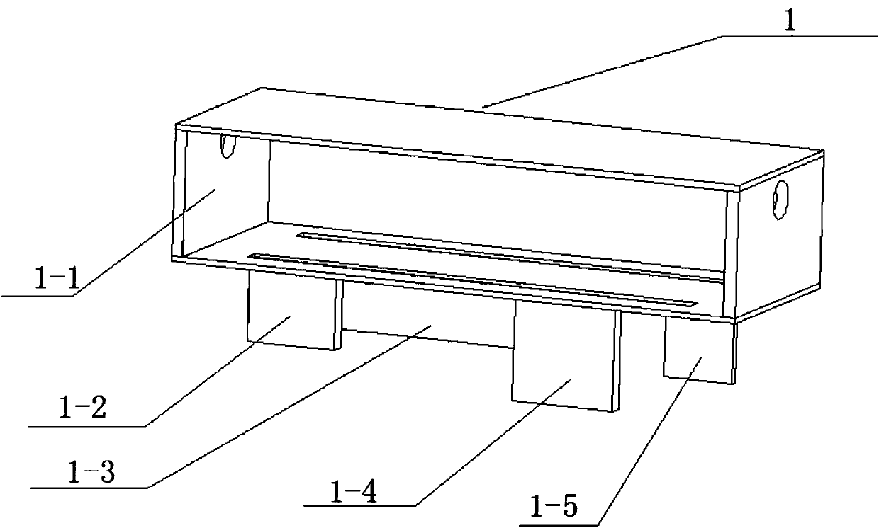
[0033] Such as figure 1 , figure 2 , image 3 , Figure 4 , Figure 5 , Image 6 , Figure 7 , Figure 8 , Picture 9 , Picture 10 with Picture 11 As shown, this embodiment will further illustrate the first embodiment. The main board block 1 includes a main frame plate 1-1, a boss I1-2, a long boss 1-3, a boss II1-4, and a boss III1- 5. The upper ends of the boss Ⅰ1-2, the long boss 1-3, the boss Ⅱ1-4 and the boss Ⅲ1-5 are all fixedly connected to the lower end of the main frame plate 1-1, and the lower end of the inner wall of the main frame plate 1-1 Two sliding grooves are provided on the upper part, and the left and right ends of the main frame plate 1-1 are provided with circular holes penetrating through them, and the circular holes are used for daily hanging and placing of the device.

Example Embodiment

Specific implementation manner three:

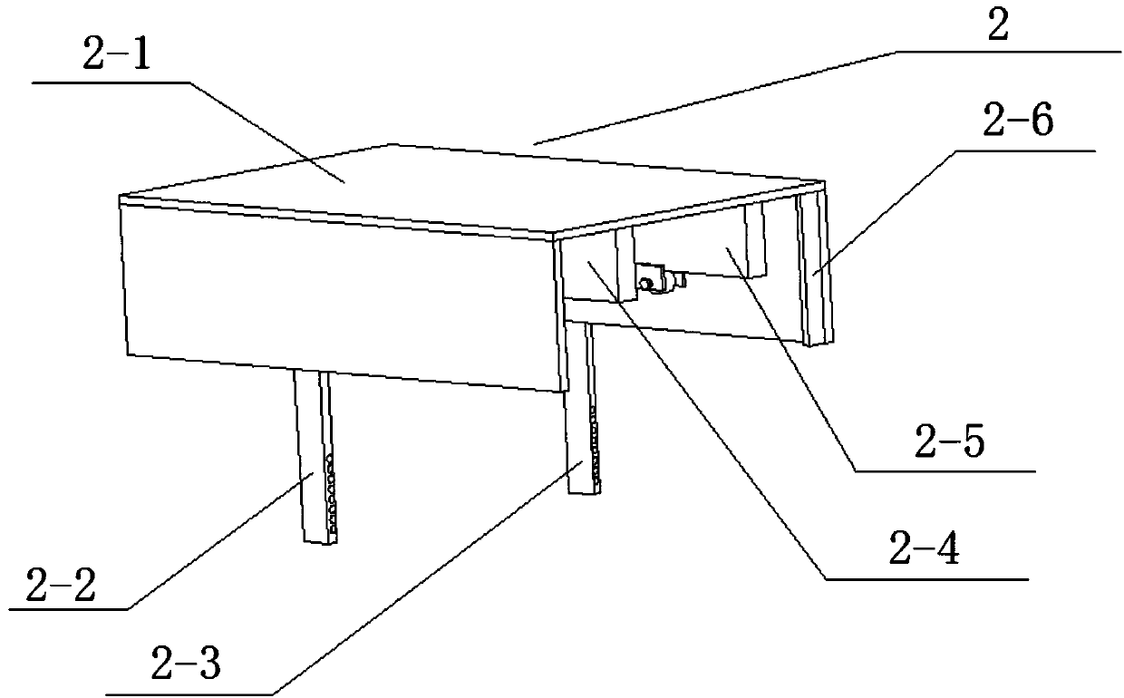
[0034] Such as figure 1 , figure 2 , image 3 , Figure 4 , Figure 5 , Image 6 , Figure 7 , Figure 8 , Picture 9 , Picture 10 with Picture 11 As shown, this embodiment further explains the first embodiment. The sliding device 2 includes a supporting plate 2-1, a connecting rod I2-2, a connecting rod II2-3, a sliding block I2-4, a sliding block II2-5, Right baffle 2-6 and left baffle 2-7, connecting rod I 2-2 and connecting rod II 2-3 are provided with a plurality of threaded holes of the same specification through left and right, the lower end of the front end of the support plate 2-1 The upper end of the connecting rod II2-3 is fixedly connected, the lower end of the rear end of the support plate 2-1 is fixedly connected to the upper end of the connecting rod I2-2, and the upper end of the sliding block I2-4 is fixedly connected to the upper end of the inner wall of the lower end of the support plate 2-1, sliding The upper end of ...


PUM


Abstract

The invention relates to kitchenware equipment, and concretely relates to a steak beating device. The invention aims to provide the steak beating device, which comprises a main plate, a sliding device, a running mechanism and a holding plate. The sliding device is slidably connected with the main plate; the running mechanism is fixedly connected onto the main plate; the sliding device is connectedwith the holding plate through a bolt. The steak beating device provided by the invention has the beneficial effects that a three-harmonic-wave drive structure of the beating mechanism is small in range, fast in frequency, and high in beating efficiency on the surface of a steak, so that the beating time is effectively reduced; at the same time, the same motor is utilized for driving a device forholding the steak to swing right and left, so that the surface of the steak is beaten uniformly through the beating mechanism, the height of the device for holding the steak can be adjusted accordingto different steaks, and the beating force is further adjusted.

Description

technical field [0001] The invention relates to a beating device, in particular to a steak beating device. Background technique [0002] The beating device is a tool for beating foods such as steaks and dough. The patent No. CN201410358 650.3 is an automatic meat paste beating machine, which relates to a machine for automatically beating lumpy raw meat into meat paste. To solve the current local characteristic hand-beating meatballs, two rectangular iron rods are used to beat the lumpy raw meat on the anvil surface until the meat is pureed. Such shortcomings as unstable quality, variable heat generation of meat paste after beating, and physical exertion. Its technical feature is that the rectangular hammer stick in the extended beating device of the air hammer beats the anvil surface rotated below in a fixed direction to form a beating area. Outflow, the coolant circulation cooling circuit inside the rectangular hammer reduces the heating state of the lumpy raw meat or me...

Claims


Application Information

Patent Timeline
IPC IPC(8): A22C7/00A22C9/00
Inventor 薛强吉
Owner 唐山市施尔得肉制品有限公司
Why Eureka
Try Eureka