
Electrical discharge machine

A discharge processing machine and discharge processing technology are applied to electric processing equipment, metal processing equipment, circuits, etc., and can solve problems such as poor production efficiency

Inactive Publication Date: 2018-02-16
FANUC LTD
View PDF1 Cites 0 Cited by
  • Summary
  • Abstract
  • Description
  • Claims
  • Application Information

AI Technical Summary

Problems solved by technology

In this way, the operator must monitor the status and perform certain operations, and the production efficiency is poor.

Method used


Image

  • Electrical discharge machine
  • Electrical discharge machine
  • Electrical discharge machine

Examples


Embodiment Construction

[0029] Referring to preferred embodiments, the electric discharge machine of the present invention will be described in detail below with reference to the drawings. In the embodiment, a wire electric discharge machine which is one type of electric discharge machine is described as an example, but an electric discharge machine in which electrodes are not wires may be used.

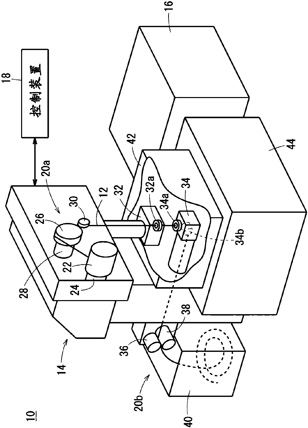
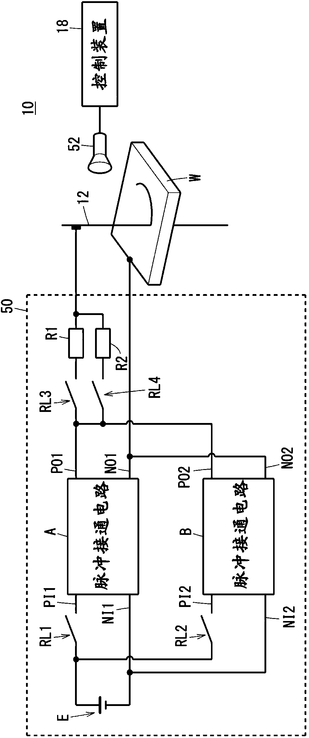
[0030] figure 1 It is a mechanical schematic configuration diagram of a wire electric discharge machine (discharge machine) 10 . The wire electric discharge machine 10 is in the machining fluid, and the wire electrode 12 and the object W to be machined (refer to figure 2 ) is a machine tool that performs electrical discharge machining on an object to be machined (workpiece) W by applying a voltage to generate an electrical discharge between electrodes (gap) formed by ). The wire electric discharge machine 10 includes a machine main body 14 , a machining fluid processing device 16 , and a control device 1...


PUM


Abstract

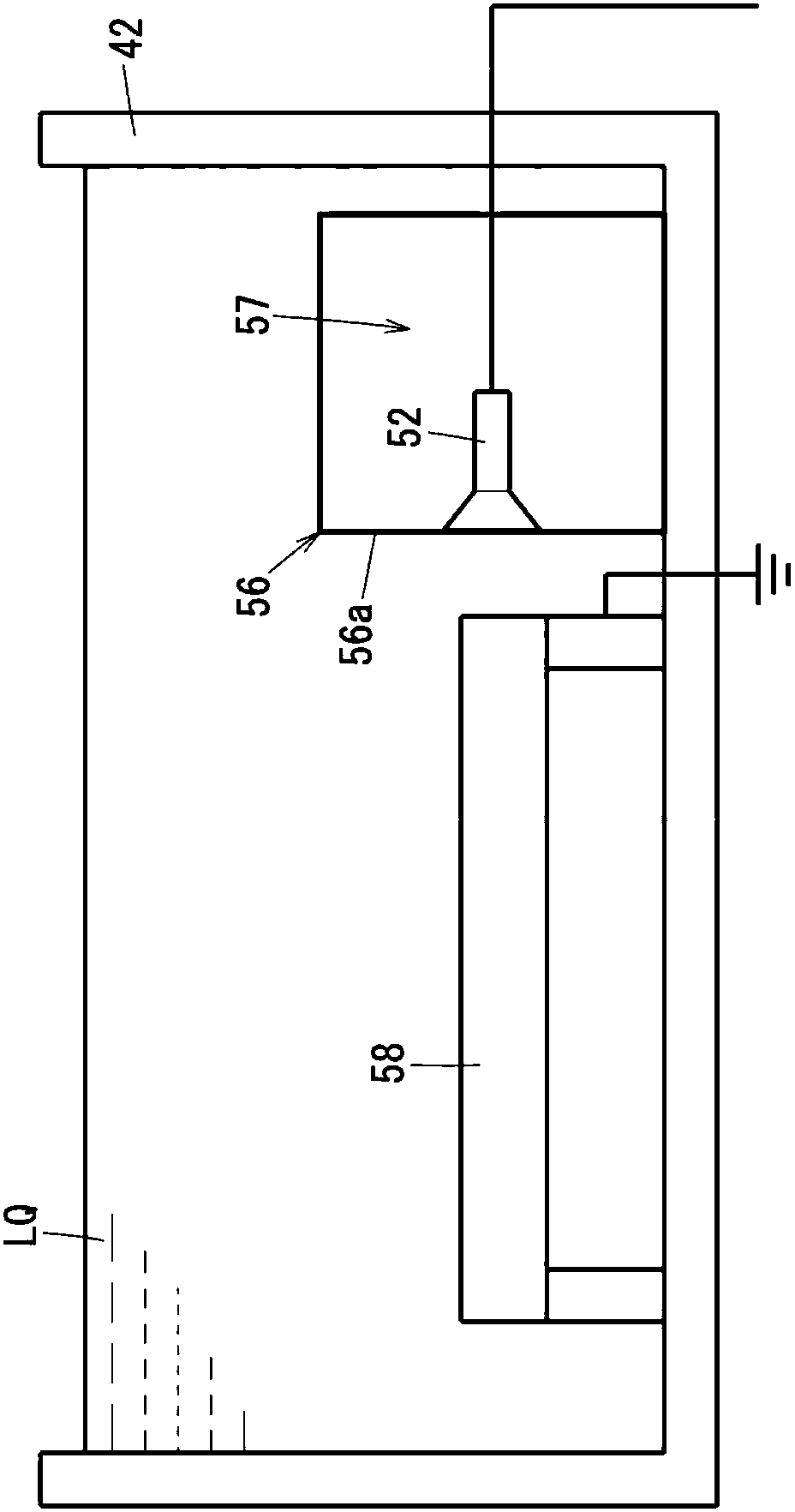
The invention provides an electrical discharge machine (10) including a work tank (42) to store the working fluid (LQ) in order to perform electrical discharge machining; a sound collector (52) to collect sound generated by electrical discharge machining and transmitted through the working fluid (LQ) stored in the work tank (42); and a controller (18) to perform a predetermined operation based onsound information collected by the sound collector (52).

Description

technical field [0001] The present invention relates to an electric discharge machine that applies a voltage to a gap formed by an electrode and an object to be machined, and flows an electric current, thereby performing electric discharge machining. Background technique [0002] Wire electrical discharge machining is widely used as a machining method capable of machining metals with high precision. Due to the high precision of wire electrical discharge machining, it may be affected by changes in the surrounding environment or equipment failures, and the processed products may become defective products. Therefore, a means of detecting failure or abnormality of the wire electric discharge machine is considered. [0003] Japanese Re-publication WO2013 / 157071 discloses a wire electrical discharge machine that detects a physical quantity indicating the state of the wire electrical discharge machine, displays the detected physical quantity, and displays the normal range of the p...

Claims


Application Information

Patent Timeline
Patent Type & Authority Applications(China)
IPC IPC(8): B23H7/02B23H7/36B23H11/00
CPCB23H7/02B23H7/36B23H11/00B23H1/02B23H7/20B23H2600/00B23H7/16
Inventor 增田政史川原章义中岛廉夫古田友之
Owner FANUC LTD
Learn More