A natural gas pipeline welding machine
What is Al technical title?
Al technical title is built by PatSnap Al team. It summarizes the technical point description of the patent document.
A natural gas pipeline and welding machine technology, which is applied in welding equipment, auxiliary welding equipment, welding/cutting auxiliary equipment, etc., can solve the problems of reducing welding effect, prone to vibration, hidden dangers of pipeline safety, etc.
Active Publication Date: 2019-05-17
浙江乔派电梯装饰有限公司
View PDF6 Cites 1 Cited by
Summary
Abstract
Description
Claims
Application Information
AI Technical Summary
This helps you quickly interpret patents by identifying the three key elements:
Problems solved by technology
Method used
Benefits of technology
Problems solved by technology
[0004] Aiming at the deficiencies of the existing technology, the object of the present invention is to provide a natural gas pipeline welding machine to solve the problem that the clips of the existing natural gas pipeline welding machine do not fit perfectly, and the pipeline is prone to vibration during welding, which reduces the welding effect and the durability of the pipeline. , which makes the pipeline a potential safety hazard
Method used
Image
Click on the blue label to locate the original text in one second.
Reading with bidirectional positioning of images and text.
Examples
Embodiment Construction
[0020] In order to make the technical means, creative features, goals and effects achieved by the present invention easy to understand, the present invention will be further described below in conjunction with specific embodiments.
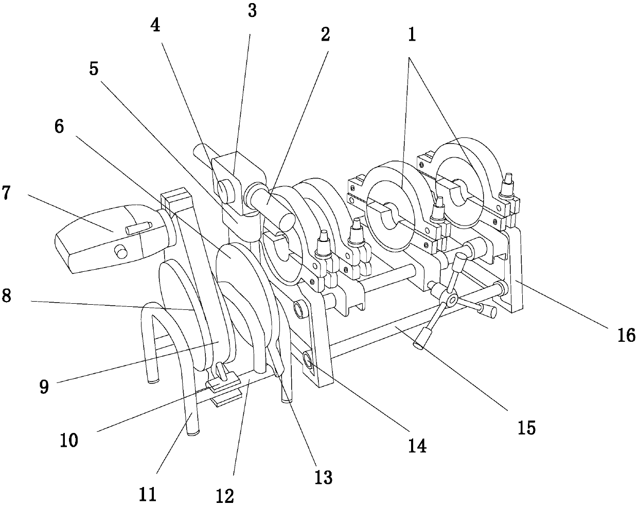
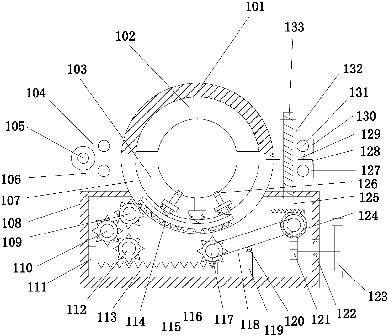
[0021] see Figure 1-Figure 4, the present invention provides a technical solution for a natural gas pipeline welding machine: its structure includes a pipeline locking structure 1, a welding head handle 2, a welding controller 3, a welding button 4, a welding ring fixing rod 5, a welding ring 6, a motor 7, a fixing Disc 8, transmission 9, swivel seat 10, support rod 11, cross bar 12, welding card seat 13, fixed ring 14, connecting rod 15, clamping support rod 16, the lower end of the clamping support rod 16 and the connecting rod 15 are about Both ends adopt embedded connection, the right end of the fixing ring 14 and the clamping support rod 16 are an integrated structure, the left end of the connecting rod 15 is connected with the inner wall of...
PUM
Abstract
The invention discloses a natural-gas pipe welding machine. The natural-gas pipe welding machine is structurally comprises a pipe locking structure, a welding head handle, a welding controller, a welding button, a welding-ring fixing rod, a welding ring, a motor, a fixing disc, a transmission, a rotating base, supporting rods, a transverse rod, a welding clamping base, fixing rings, connecting rods and clamping supporting rods, wherein the lower ends of the clamping supporting rods are connected with the left ends and the right ends of the connecting rods in an embedded mode, the right ends ofthe fixing rings and the clamping supporting rods are integrally formed, the left ends of the connecting rods penetrate through the inner walls of the fixing rings, the connecting rods are perpendicular to the left ends of the clamping supporting rods, and the lower ends of the supporting rods and the left end and the right end of the transverse rod are welded. According to the natural-gas pipe welding machine, the pipe clamping structure is structurally arranged, an upper clamping block and a lower clamping block tightly clamp the pipe, waggling can be avoided, welding is stably carried outaccordingly, the welding effect is improved, the service life of the pipe is thus prolonged, and the use hidden danger is reduced.
Description
technical field [0001] The invention relates to a natural gas pipeline welding machine, which belongs to the field of natural gas pipeline welding machines. Background technique [0002] Pipelines that transport natural gas (including associated gas produced in oil fields) from mining sites or processing plants to urban gas distribution centers or industrial enterprise users are also called gas transmission pipelines. The use of natural gas pipelines to transport natural gas is the only way to transport large quantities of natural gas on land. [0003] However, the clamping blocks of the existing natural gas pipeline welding machine do not fit perfectly, and the pipeline is prone to vibration during welding, which reduces the welding effect and durability of the pipeline, causing potential safety hazards in the pipeline. Contents of the invention [0004] Aiming at the deficiencies of the existing technology, the object of the present invention is to provide a natural gas...
Claims
Application Information
Patent Timeline
Application Date:The date an application was filed.
Publication Date:The date a patent or application was officially published.
First Publication Date:The earliest publication date of a patent with the same application number.
Issue Date:Publication date of the patent grant document.
PCT Entry Date:The Entry date of PCT National Phase.
Estimated Expiry Date:The statutory expiry date of a patent right according to the Patent Law, and it is the longest term of protection that the patent right can achieve without the termination of the patent right due to other reasons(Term extension factor has been taken into account ).
Invalid Date:Actual expiry date is based on effective date or publication date of legal transaction data of invalid patent.