
Grinding device capable of following steel nails in self-adaptive mode

A self-adaptive, steel nail technology, which is applied in the direction of grinding drive devices, machine tools suitable for grinding workpiece edges, grinding machines, etc., can solve the problem that the steel nail grinding device cannot self-adaptively follow the size and changes of steel nails, and achieve installation And easy disassembly, strong practicability, and the effect of expanding the scope of use

Inactive Publication Date: 2018-02-16
ZHENGZHOU QISHUO ELECTRONICS TECH CO LTD
View PDF0 Cites 8 Cited by
  • Summary
  • Abstract
  • Description
  • Claims
  • Application Information

AI Technical Summary

Problems solved by technology

[0003] The object of the present invention is to provide a grinding device that can self-adaptively follow the steel nail in view of the problem that the above-mentioned existing steel nail grinding device cannot self-adaptively follow the size change of the steel nail

Method used


Image

  • Grinding device capable of following steel nails in self-adaptive mode
  • Grinding device capable of following steel nails in self-adaptive mode
  • Grinding device capable of following steel nails in self-adaptive mode

Examples


Embodiment 1

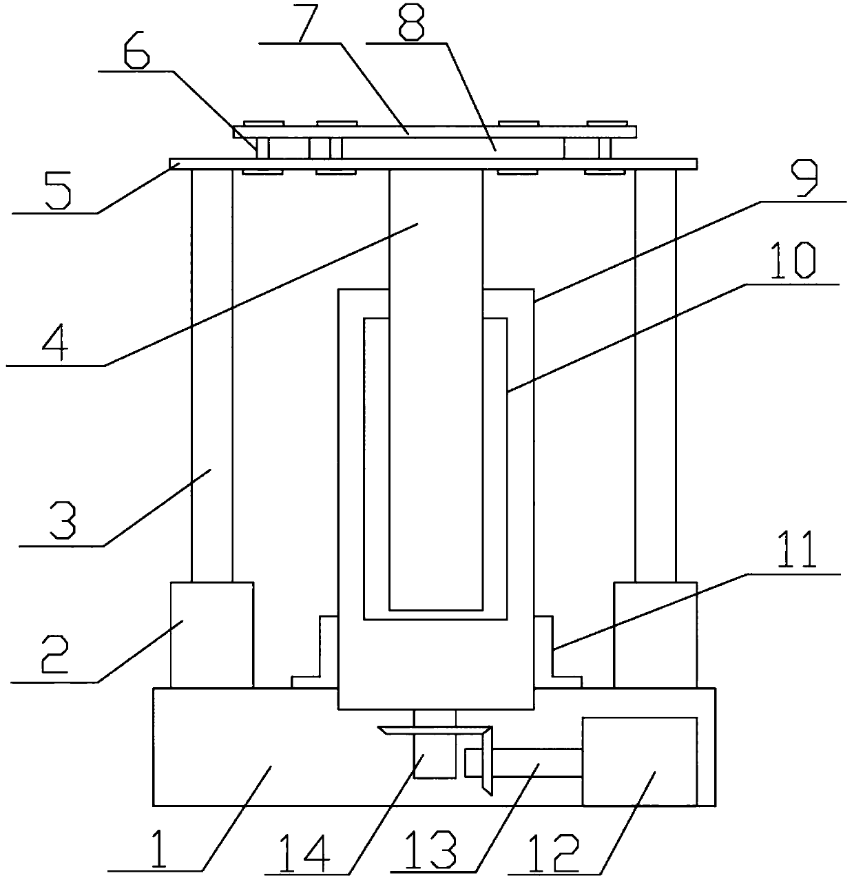
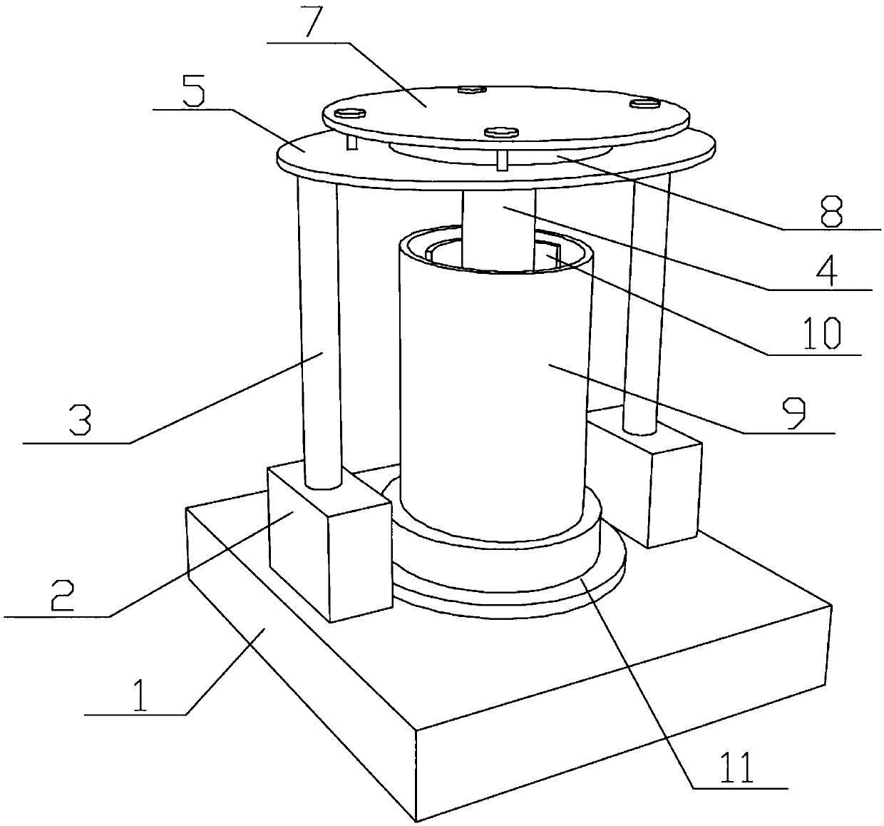
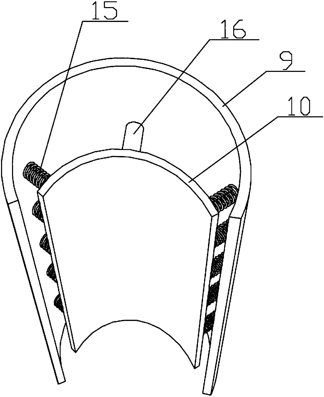
[0026] A grinding device capable of self-adaptively following steel nails, comprising a steel nail fixing device, a base 1 is provided below the steel nail fixing device, and a rotatable grinding cylinder 9 with a top opening is fixed on the base 1, and the grinding cylinder 9 An arc-shaped piece 10 made of elastic material is arranged inside, the outer side of the arc-shaped piece 10 is fixed to the inner wall of the grinding cylinder 9 by a fixed rod 16, and the outer side of the arc-shaped piece 10 near the side is connected to the inner wall of the grinding cylinder 9 by a spring 15, The inner side of the arc part 10 is provided with steel wire bristles for grinding the nail body 4 .

[0027] When the present invention is in use, after the steel nail is fixed by the steel nail fixing device, the nail body 4 of the steel nail extends into the grinding cylinder 9, and the steel wire bristles on the inner side of the arc-shaped part 10 are kept under the action of the fixing r...

Embodiment 2

[0029] Based on Embodiment 1, a bearing seat 11 is fixed on the base 1, and a bearing is installed in the bearing seat 11, and the lower end of the grinding cylinder 9 is connected to the bearing; the bottom of the grinding cylinder 9 extends into the base 1 and is connected to a rotating shaft 14. The base 1 is provided with a motor 12 for driving the rotating shaft 14 to rotate. The bearing can play the role of supporting the grinding cylinder 9 on the one hand, and on the other hand, can also ensure that the grinding cylinder 9 rotates. The present invention drives the rotating shaft 14 to rotate through the motor 12, thereby driving the grinding cylinder 9 to rotate.

Embodiment 3

[0031] Based on the second embodiment, the rotating shaft 14 and the output shaft 13 of the motor 12 are transmitted through gears. Gear transmission has the characteristics of high efficiency, compact structure, reliable operation and long life.


PUM


Abstract

The invention discloses a polishing device capable of self-adaptively following steel nails, comprising a steel nail fixing device, a base is arranged under the steel nail fixing device, and a rotatable grinding cylinder with an opening at the top is fixed on the base, the grinding cylinder There is an arc-shaped piece made of elastic material inside. The outer side of the arc-shaped piece is fixed to the inner wall of the grinding cylinder through a fixing rod. The outer side of the arc-shaped piece near the side is connected to the inner wall of the grinding cylinder through a spring. Steel wire bristles for grinding nail body. The radian of the arc-shaped part of the present invention can follow the change of the diameter of the steel nail, that is, the present invention can self-adaptively follow the change of the size of the steel nail, which significantly expands the scope of application. In addition, the invention controls the steel nails to move up and down through the air cylinder, so that the grinding is thorough, and it is also applicable to steel nails of different lengths, which further expands the scope of use.

Description

technical field [0001] The invention belongs to the technical field of steel nail production equipment, and in particular relates to a grinding device capable of self-adaptively following steel nails. Background technique [0002] Steel nails are steel wire products used for nailing objects. They are widely used in various fields such as industry, agriculture, construction, and civil use. They are mainly used for fixing objects with small axial separation force and small radial shear force. Easy to use and fast nailing. The existing steel nail derusting and grinding device is only suitable for steel nails of specific specifications, and the grinding device cannot adapt to changes in the size of the steel nail, which greatly limits the scope of use of the grinding device. Contents of the invention [0003] The object of the present invention is to provide a grinding device that can self-adaptively follow the steel nails for the above-mentioned problem that the existing ste...

Claims


Application Information

Patent Timeline
IPC IPC(8): B24B19/16B24B27/033B24B41/06B24B47/16B24B47/12B24D13/10
CPCB24B19/16B24B27/033B24B41/06B24B47/12B24B47/16B24D13/10
Inventor 高翔
Owner ZHENGZHOU QISHUO ELECTRONICS TECH CO LTD
Learn More