A door locking mechanism of a new energy vehicle charging pile

A new energy vehicle and locking mechanism technology, applied in electric vehicle charging technology, charging stations, electric vehicles, etc., can solve the problems of reduced working life, high production cost, and easy aging of charging piles, so as to improve work efficiency and work simple effect

Active Publication Date: 2019-05-14
ANHUI KECHUANG NEWENERGY TECH CO LTD
View PDF6 Cites 0 Cited by
  • Summary
  • Abstract
  • Description
  • Claims
  • Application Information

AI Technical Summary

Problems solved by technology

[0007] In order to overcome the deficiencies of the existing technical solutions, the present invention provides a hatch locking mechanism for charging piles of new energy vehicles, which not only solves the problem of complex price comparison, inconvenient manufacturing process, and high manufacturing cost of traditional charging pile hatch locking mechanisms. It also solves the problem that the existing charging pile cabin door locking mechanism lacks an indicator light to remind the user whether the charging pile is working normally, which makes it inconvenient for the user to use, and also lacks an alarm device so that the user can know that the charging pile is under the action of the alarm device. After a failure, the staff can be notified immediately to carry out maintenance work to improve work efficiency, and it also solves the problem that the existing charging pile door locking mechanism is often placed in the open air, causing the charging pile to age easily and reduce the working life.

Method used


Image

  • A door locking mechanism of a new energy vehicle charging pile
  • A door locking mechanism of a new energy vehicle charging pile
  • A door locking mechanism of a new energy vehicle charging pile

Examples


Embodiment

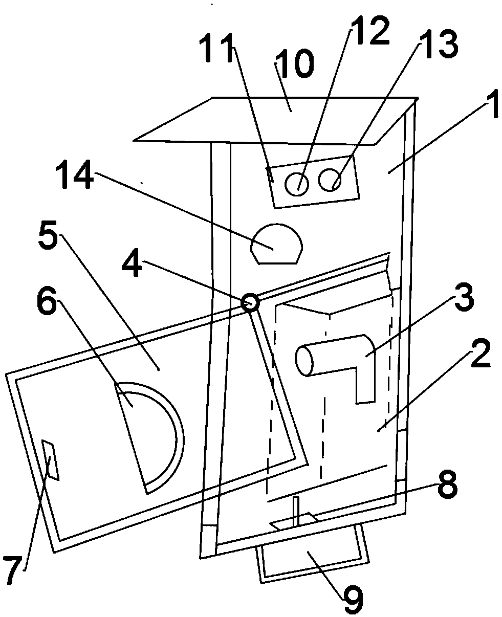
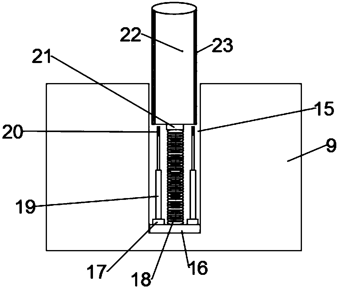
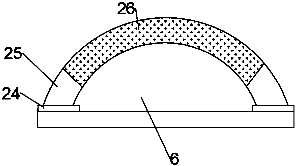
[0027] like figure 1 , figure 2 and image 3 The shown invention provides a door locking mechanism for a new energy vehicle charging pile, including a charging pile 1, a rectangular parallelepiped charging box 2 is arranged at the bottom of the charging pile 1, and a charger 3 is arranged inside the charging box 2 , the upper left corner of the charging box 2 is provided with a rotating hinge 4, the outside of the charging box 2 is provided with a rectangular charging box cover 5 with the same size and shape as the charging box 2, and the surface of the charging box cover 5 is provided with a semicircular handle 6, the bottom of the rectangular charging box cover 5 is provided with a rectangular upper lock ring 7, the bottom of the charging pile 1 is provided with a lower lock ring 8, and a lock cylinder box 9 is provided below the lower lock ring 8, and the charging The top of the pile 1 is provided with a rainproof layer 10, the middle of the lock cylinder box 9 is provid...


PUM


Abstract

The invention discloses a port locking mechanism for a charging pile for a new energy vehicle. The port locking mechanism for the charging pile for the new energy vehicle comprises a charging pile. Acuboid charging box is arranged at the lower part of the interior of the charging pile. A charger is arranged in the charging box. A rotating hinge is arranged at the upper left corner of the chargingbox. A charging box cover is provided with a semicircular handle on the surface. A rectangular upper locking ring is arranged at the bottom of the rectangular charging box cover. A lower locking ringis arranged at the bottom of the charging pile. A lock cylinder box is arranged below the lower locking ring. A fixed base is arranged at the bottom of a concave groove. Controllers are arranged at the two ends of the upper surface of the fixed base. A spring is arranged on the upper surface of the fixed base. A top end is vertically arranged on the top of the spring having memory. A lock cylinder in the shape of a cylinder is vertically arranged on the top end. The port locking mechanism for the charging pile for the new energy vehicle solves the problems that the traditional port locking mechanisms of the charging piles are high in production cost, the work efficiency of the existing port locking mechanisms of the charging piles cannot be improved, and the existing port locking mechanisms of the charging piles are short in service life.

Description

technical field [0001] The invention relates to the technical field of automobile charging piles, in particular to a door locking mechanism of a new energy automobile charging pile. Background technique [0002] The charging pile is an electric vehicle charging station, which looks like a parking stopwatch. Charging piles can be divided into DC charging piles, AC charging piles and AC-DC integrated charging piles. An AC charging pile can charge one or more cars at the same time, and the charging time of the AC charging pile from empty to full is 6 to 8 hours. The charging pile can realize timing, electricity meter, and amount charging, and can be used as a citizen's electricity purchase terminal. [0003] The application number is 201220529704.4, which is an invention patent for an automatic closing charging pile hatch locking mechanism. The advantage of this invention is that the automatic closing charging pile hatch locking mechanism provided by this invention can Type ...

Claims


Application Information

Patent Timeline
Patent Type & Authority Patents(China)
IPC IPC(8): B60L53/31E05B1/00E05B65/52
CPCB60L53/31E05B1/00E05B65/00Y02T10/70Y02T10/7072Y02T90/12
Inventor 各阿杰
Owner ANHUI KECHUANG NEWENERGY TECH CO LTD
Why Eureka
Try Eureka