Construction site dust removing device

A kind of dust removal equipment and construction site technology, which is applied to mixers, mixers using liquid separation agents, and mixers with rotating stirring devices, etc. It can solve the problem of poor mixing effect of cold water and normal temperature water, inability to fold the sprinkling part, and easy cold and hot water Uneven problems, achieve compact structure, improve dust removal range and uniformity of dust removal, and reduce labor load

Inactive Publication Date: 2018-02-16
广州尚儒自控系统工程有限公司
View PDF5 Cites 1 Cited by
  • Summary
  • Abstract
  • Description
  • Claims
  • Application Information

AI Technical Summary

Problems solved by technology

[0002] In construction sites and other places, due to the large amount of dust generated during construction, the dust passing through the workers' respiratory tract will seriously affect the health of the workers' lungs. The construction site sprinkler is generally integrated, the sprinkling part is stretched out and cannot be folded, it occupies a large space, and it is difficult to move, and when the weather is hot, it is necessary to add ice water or ice cubes to the water to achieve the function of cooling the construction site while removing dust. Traditional The water in the dedusting mist cannon tends to be hot and cold, and the mixing effect of cold water and normal temperature water is poor

Method used


Image

  • Construction site dust removing device
  • Construction site dust removing device
  • Construction site dust removing device

Examples


Embodiment Construction

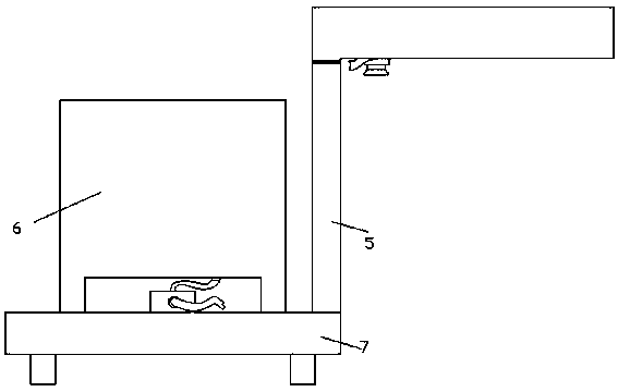
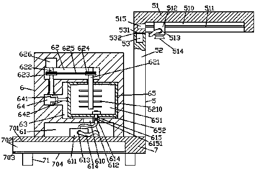
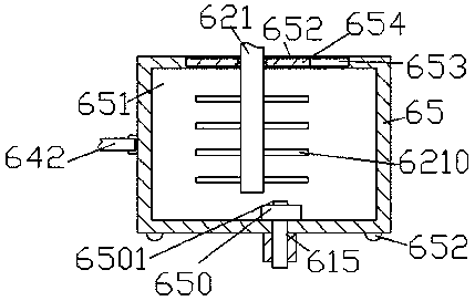
[0024] Such as Figure 1-Figure 5As shown, a construction site dust removal equipment of the present invention includes a base 7 and a dust removal box 6 fixed on the top of the base 7, and a dust removal device 5 is provided on the base 7 on the right side of the dust removal box 6, The bottom of the dust removal box 6 is provided with a first channel groove 61, and the dust removal box 6 above the first channel groove 61 is provided with an embedded groove 64 and a sliding cavity 63, and the embedded groove 64 is located in the sliding The middle position of the inner wall on the left side of the cavity 63 and the right end of the insertion groove 64 and the left end of the sliding cavity 63 pass through. The sliding cavity 63 is provided with an atomization box 65. A knuckle shaft 641 is connected by rotation and fit, and a push-pull rod 642 is flexibly connected between the knuckle shaft 641 and the left end of the atomization box 65. A storage chamber 651 is provided insi...


PUM


Abstract

The invention discloses a construction site dust removing device. The construction site dust removing device includes a base and a dust removing box which is fixed on the top of the base; a dust removing apparatus is arranged on the base on the right side of the dust removing box; a first channel groove is formed in the bottom of the dust removing box; an embedding groove and a sliding chamber areformed in the dust removing box above the first channel groove; the embedding groove is positioned in the center of a left inner wall of the sliding chamber, and a right end of the embedding groove communicates with a left end of the sliding chamber; an atomization box is arranged in the sliding chamber; a bevel shaft is rotatably and internally connected to the embedding groove; a push-pull rodis flexibly connected between the bevel shaft and a left end of the atomization box; a storage chamber is formed in the atomization box; a second channel groove is formed in the top of the storage chamber; guide grooves are formed in a left inner wall and a right inner wall of the second channel groove; and a guide plate is slidingly connected between the guide grooves at the left side and the right side. The construction site dust removing device is compact in structure, is reasonable in design, is even in water temperature, can improve the working efficiency, can be easily stored, is small in size, can enlarge the dust removing range, and can improve the evenness of dust removing.

Description

technical field [0001] The invention relates to the field of dust removal, in particular to a construction site dust removal equipment. Background technique [0002] In construction sites and other places, due to the large amount of dust generated during construction, the dust passing through the workers' respiratory tract will seriously affect the health of the workers' lungs. The construction site sprinkler is generally integrated, the sprinkling part is stretched out and cannot be folded, it occupies a large space, and it is difficult to move, and when the weather is hot, it is necessary to add ice water or ice cubes to the water to achieve the function of cooling the construction site while removing dust. Traditional The water in the dedusting mist cannon tends to be hot and cold unevenly, and the mixing effect of cold water and normal temperature water is poor. Contents of the invention [0003] The technical problem to be solved by the present invention is to provid...

Claims


Application Information

Patent Timeline
Patent Type & Authority Applications(China)
IPC IPC(8): E01H3/00B01D47/06B01F7/18
CPCB01D47/06E01H3/00B01F27/90
Inventor 吴敏俊付天龙
Owner 广州尚儒自控系统工程有限公司
Why Eureka
Try Eureka