Dehumidification apparatus and power cabinet

A power cabinet, humidity technology, applied in humidity control, non-electric variable control, instruments, etc., can solve the problems of power equipment performance and service life decline, and achieve the effect of ensuring performance and service life

Inactive Publication Date: 2018-02-16
国网山东省电力公司泗水县供电公司 +1
View PDF4 Cites 6 Cited by
  • Summary
  • Abstract
  • Description
  • Claims
  • Application Information

AI Technical Summary

Problems solved by technology

[0006] In view of this, the object of the present invention is to provide a dehumidification device and a power cabinet t

Method used


Image

  • Dehumidification apparatus and power cabinet
  • Dehumidification apparatus and power cabinet
  • Dehumidification apparatus and power cabinet

Examples


Embodiment 1

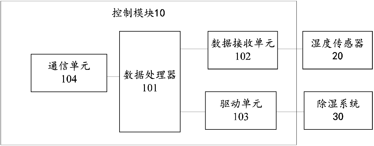
[0031] An embodiment of the present invention provides a dehumidification device, which can be installed inside the power cabinet to perform dehumidification operations on the power cabinet, such as figure 1 A schematic structural diagram of a dehumidification device is shown, the dehumidification device includes: a control module 10 , and a humidity sensor 20 and a dehumidification system 30 connected to the control module 10 .

[0032] The humidity sensor 20 is used to detect the humidity parameters of the environment where the dehumidifier is located, and send the humidity parameters to the control module 10 .

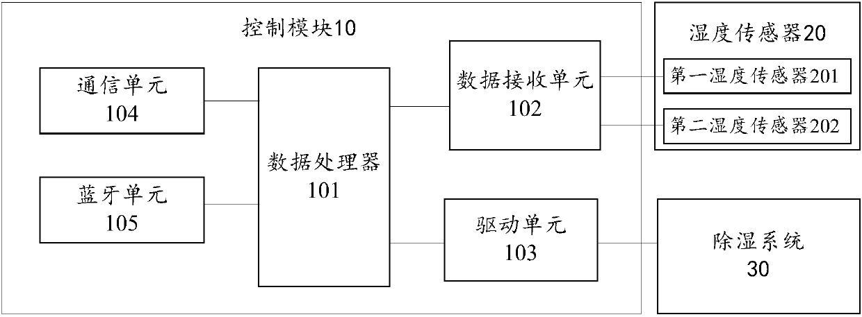
[0033] The control module 10 includes a data processor 101, and a data receiving unit 102 connected to the data processor 101, a drive unit 103 and a communication unit 104; wherein the data receiving unit 102 is connected to the humidity sensor 20, and the drive unit 103 is connected to the dehumidification system 30 ;

[0034]The data receiving unit 102 is used t...

Embodiment 2

[0051] On the basis of the above-mentioned embodiments, the embodiment of the present invention also provides a power cabinet, the interior of the power cabinet is provided with the dehumidification device described in the first embodiment above; the cabinet body of the power cabinet is provided with a drainage box for Receive the moisture discharged from the dehumidification unit.

[0052] During specific implementation, the above-mentioned power cabinet can be a power distribution cabinet, a switch cabinet, etc., and the side of the cabinet body of the above-mentioned dehumidification device used for installation and fixing can be provided with a fixing frame, and threaded holes are set on the fixing frame, so that the dehumidification device can pass through the screw. It is fixed inside the box body of the power cabinet, and when installing, the dehumidification device must be placed vertically with the water outlet of the water pipe facing down. There is more than 5cm of ...


PUM


Abstract

The present invention provides a dehumidification apparatus and a power cabinet, and relates to the technical field of power equipment. The dehumidification apparatus includes a control module, and ahumidity sensor and a dehumidification system which are connected to the control module. The control module includes a data processor, a data receiving unit, a driving unit and a communication unit; the data processor is configured to receive a humidity parameter; when the humidity parameter exceeds a preset humidity threshold, the dehumidification system is driven by the driving unit to start dehumidification, and the communication unit is connected with the upper computer to send the humidity parameter to the upper computer and to receive a driving signal sent by the upper computer. The dehumidification system is driven by the driving unit to start the dehumidification work. The dehumidification apparatus and the power cabinet provided by the present invention help the staff to monitor the humidity of the environment in which the power cabinet is located in real time to take dehumidification work, so as to prevent the power equipment from being in a humid environment for a long timeand help to ensure the performance and the service life of the power equipment.

Description

technical field [0001] The invention relates to the technical field of power equipment, in particular to a dehumidification device and a power cabinet. Background technique [0002] In the humid environment, the threats to power facilities are becoming more and more obvious, and the humid environment has a great impact on the safe operation of electrical equipment. In electrical engineering, high humidity is the main factor for electrical equipment accidents. [0003] The failure-prone season of electrical equipment is in the wet spring, when the temperature changes suddenly or day and night, and the seasons with large temperature differences, such as sudden drop, rise, etc., are often prone to failure of electrical equipment. Moist air is likely to reduce the insulation strength of electrical equipment: on the one hand, the humidity is too high, which reduces the insulation performance of the air, and many places in the power switchgear are insulated by air gaps; on the ot...

Claims


Application Information

Patent Timeline
IPC IPC(8): G05D22/02
Inventor 冯磊陈宏伟张新强王宗山张长斌马建华蒋仲俊张建军杨琳徐同锋
Owner 国网山东省电力公司泗水县供电公司
Why Eureka
Try Eureka