Sealing assembly

A technology of sealing components and sealing parts, which is applied in the direction of electrical components, parts of connecting devices, base/housing, etc., can solve the problems of high cost, large tightening torque, and no obvious advantages of rubber sealing rings, and achieve low cost and applicable Strong performance, guaranteed performance and service life

Active Publication Date: 2019-10-25
CHINA AVIATION OPTICAL-ELECTRICAL TECH CO LTD
View PDF3 Cites 0 Cited by
  • Summary
  • Abstract
  • Description
  • Claims
  • Application Information

AI Technical Summary

Problems solved by technology

[0003] The mating part of the connector head seat is also sealed with a metal sealing ring. The metal sealing ring has certain advantages in high temperature resistance and radiation resistance, but the tightening torque is relatively large, and a new metal sealing ring needs to be replaced every time it is disassembled. The cost is high, and there is no obvious advantage over the rubber sealing ring in the design basis accident simulation test

Method used


Image

  • Sealing assembly
  • Sealing assembly
  • Sealing assembly

Examples


Embodiment Construction

[0031] In order to further illustrate the technical means and technical effects adopted by the present invention, the present invention will be described in detail below in conjunction with specific embodiments.

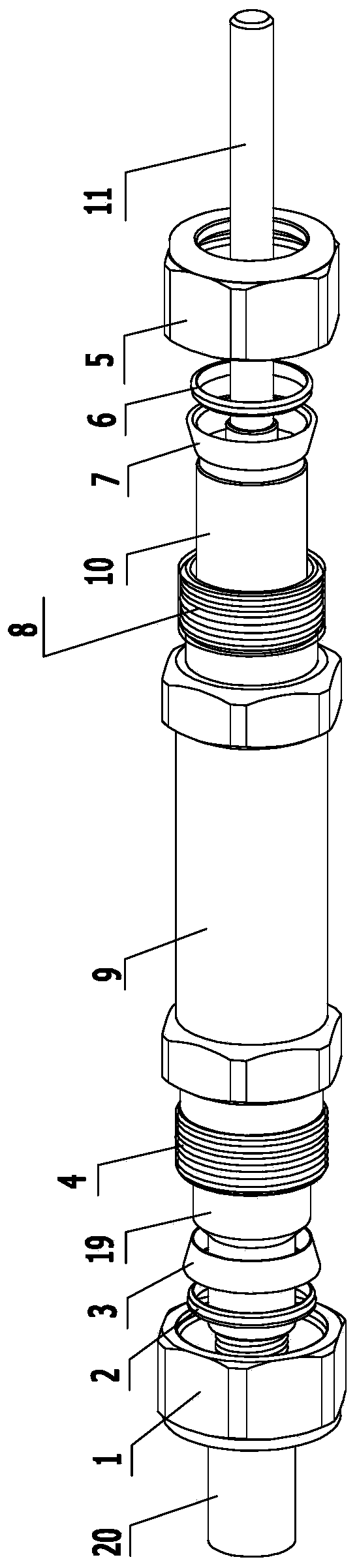
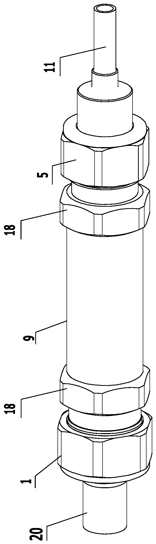
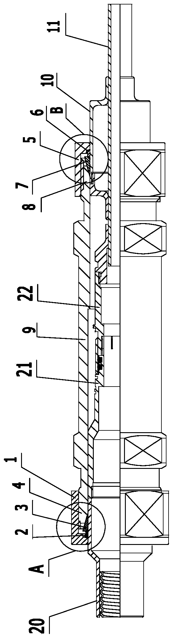
[0032] Such as figure 1 As shown, the present invention includes a straight sleeve for wrapping and sealing the plug and socket of the connector, a nut for threaded connection with the threaded connecting portion at both ends of the straight sleeve, and a nut arranged on the screw. The front sleeve and the rear sleeve which play a sealing role between the cap and the corresponding connecting part. For the convenience of description, the sealing assembly at the left end of the straight sleeve 9 is marked as nut A 1, rear sleeve A 2, front sleeve A 3, and connecting part A 4, and the sealing assembly at the right end of the straight sleeve is marked as nut B 5, rear sleeve B 6, front cover B 7, connecting part B 8, and define that the front cover A is located in front...


PUM


Abstract

The invention relates to a sealing assembly, which comprises a straight sleeve, nuts for being in threaded connection with connecting parts with threads at the two ends of the straight sleeve, and a front sleeve and a rear sleeve arranged between the nuts and the corresponding connecting parts to play a sealing role. After the sealing assembly and a part to be sealed are assembled in place, A conical surface I at the back end of the inner wall of one connecting part and a conical surface II on the outer wall of the front sleeve are closely connected to form a seal, a conical surface III at therear end of the front sleeve and a conical surface IV on the rear sleeve are matched to form a seal, a conical surface V on the rear sleeve and a conical surface VI in one nut are closely matched toform a seal, the front end of the front sleeve is compressed in a gradual-diameter cavity I formed between the conical surface I and the part to be sealed, the front end of the rear sleeve is compressed in a gradual-diameter cavity II formed between the conical surface III and the part to be sealed, so that the part to be sealed is sealed in the straight sleeve to prevent steam from entering the inside. The sealing assembly can prevent the steam from entering the inside through a rubber sealing ring at the head-base plugging fit position of connectors and improve the environmental tolerance ofa connector assembly to a designed reference accident.

Description

technical field [0001] The invention relates to a sealing assembly. Background technique [0002] The connection between the connector and the cable can be sealed by glue filling, welding, etc., without disassembly, and reliable sealing can be guaranteed through process control. The mating part of the connector head seat is often sealed with a rubber sealing ring due to the need for separation and mating. The rubber sealing ring has a simple installation structure, small operating torque, and can be plugged and pulled out many times. It has a good sealing effect in water-sealed and air-sealed occasions under general conditions. However, in the high-temperature, high-pressure steam environment of nuclear power plant design basis accidents, because the rubber material has a certain air permeability, it is difficult for the rubber sealing ring structure to 100% block the moisture from entering. It has been verified by many tests that the insulation resistance of connector com...

Claims


Application Information

Patent Timeline
IPC IPC(8): H01R13/52
CPCH01R13/5219
Inventor 薛欢欢江浪邵明坤赵鹏坤牛志军
Owner CHINA AVIATION OPTICAL-ELECTRICAL TECH CO LTD
Why Eureka
Try Eureka