Remote switch for function amplifier

A technology of remote switch and power amplifier, applied in the field of remote switch, can solve the problem of not being able to control the switch remotely, and achieve the effects of effective remote control, simple structure and easy installation

Inactive Publication Date: 2018-02-16
成都西井科技有限公司
View PDF6 Cites 0 Cited by
  • Summary
  • Abstract
  • Description
  • Claims
  • Application Information

AI Technical Summary

Problems solved by technology

[0005] The present invention aims to solve the problem that the switch cannot be remotely controlled in the prior art, provides a remote switch for the functional amplifier, and adds a radio frequency circuit for wireless communication

Method used


Image

  • Remote switch for function amplifier
  • Remote switch for function amplifier
  • Remote switch for function amplifier

Examples


Embodiment

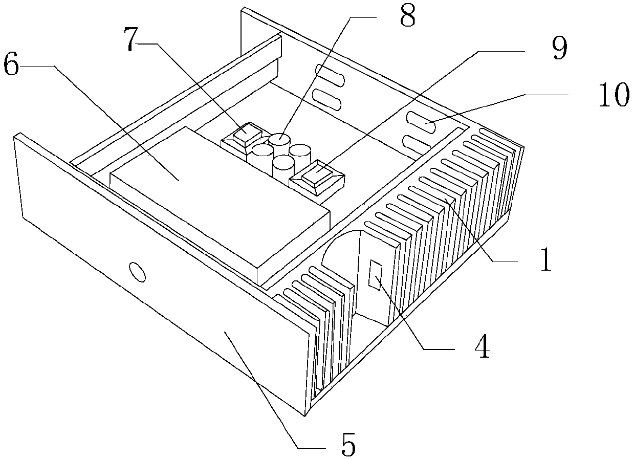
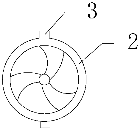
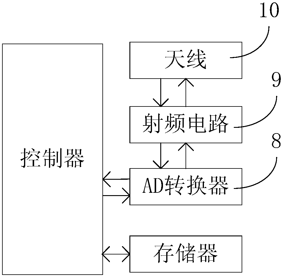
[0027] Such as figure 1 , 2 , shown in 3, is used for the remote switch of functional amplifier, comprises power amplifier 6, controller, AD converter 8, radio frequency circuit 9, antenna 10, memory; Described controller and memory are all arranged in the inside of power amplifier 6, And the controller is electrically connected to the memory; the AD converter 8 is electrically connected to the controller and the radio frequency circuit 9 , and the radio frequency circuit 9 is electrically connected to the antenna 10 . The above-mentioned radio frequency circuit 9 can realize communication with the data center through the antenna 10, so as to complete communication tasks such as remote power on and off.

[0028] The above-mentioned remote switch for the functional amplifier also includes at least 10 heat sinks 1 and temperature sensors 7; the heat sinks 1 are neatly arranged on one side of the power amplifier 6, and an empty slot is arranged between the heat sinks 1 , the fa...


PUM


Abstract

The invention discloses a remote switch for a function amplifier. The remote switch comprises a power amplifier, a controller, an AD (Analogue / Digital) converter, a radio-frequency circuit, an antennaand a memory, wherein the controller and the memory are both arranged inside the power amplifier; in addition, the controller is electrically connected with the memory; the AD converter is electrically connected with the controller and the radio-frequency circuit; and the radio-frequency circuit is electrically connected with the antenna. The radio-frequency circuit can communicate with a data center through the antenna, so that communication work of a remote switching machine and the like is finished.

Description

technical field [0001] The invention relates to an over-temperature protection device, in particular to a remote switch for a functional amplifier. Background technique [0002] Since 1974, the Plessey company of the United States has used GaAs FETs as active devices and GaAs semi-insulating substrates as carriers to successfully develop the world's first MMIC amplifier. Driven by aspects), the development of MMIC is very rapid. In the 1980s, with the development and progress of molecular beam epitaxy, metal organic chemical vapor deposition technology (MOCVD) and deep submicron processing technology, MMIC developed rapidly. In 1980, the High Electron Mobility Transistor (HEMT) was developed by the laboratories of Thomson-CSF and Fujitsu, which has achieved continuous breakthroughs and innovations in material structure. In 1985, Maselink used a pseudo-HEMT (PHEMT) made of an InGaAs channel with better performance, which made HEMT develop towards the direction of lower nois...

Claims


Application Information

Patent Timeline
Patent Type & Authority Applications(China)
IPC IPC(8): G08C17/02H04B1/40H05K7/20
CPCG08C17/02H04B1/40H05K7/20209
Inventor 陈维刚
Owner 成都西井科技有限公司
Why Eureka
Try Eureka