CO<2> laser power grid foreign matter remover with I-beam structure

A foreign object removal and I-beam technology, applied in lasers, laser parts, overhead line/cable equipment, etc., can solve the problems of increasing the weight of the launch device, the length of the optical system, and the difficulty of transportation, and reduce the weight. , the effect of reducing the length

Active Publication Date: 2018-02-16
BEIJING INST OF ELECTRONICS SYST ENG
View PDF5 Cites 0 Cited by
  • Summary
  • Abstract
  • Description
  • Claims
  • Application Information

AI Technical Summary

Problems solved by technology

The emission light path of the existing scavenger is linear, in CO 2 After installing the beam shaping system after the laser tube, the length of the overall optical system is longer, which is very unfavorable for operation and transportation
In addition, the existing scavenger emission device adopts a cylindrical structure, and the emission optical path is installed and fixed on the wall of the cylinder. In order to ensure the stability of the optical path, the wall of the emission cylinder needs to be strengthened and thickened, which increases the weight of the emission device and increases the cost of transportation and handling. difficulty

Method used


Image

  • CO&lt;2&gt; laser power grid foreign matter remover with I-beam structure
  • CO&lt;2&gt; laser power grid foreign matter remover with I-beam structure

Examples


Embodiment Construction

[0021] The present invention is described in detail by the following examples. It is necessary to point out that this example is only used to further illustrate the present invention, and can not be interpreted as limiting the protection scope of the present invention. Those skilled in the art can according to the above invention Some non-essential improvements and adjustments have been made to the content. In the case of no conflict, the embodiments and the features in the embodiments of the present invention can be combined with each other.

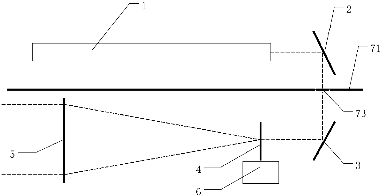
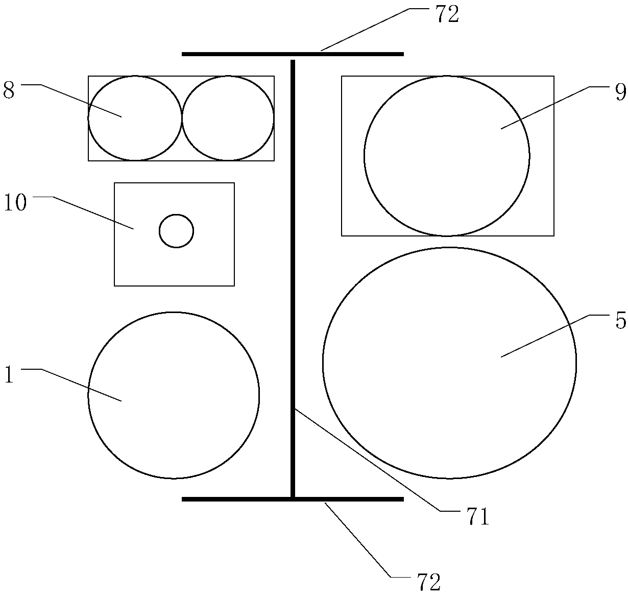
[0022] figure 1 For the present invention CO 2 Schematic diagram of the layout of the laser transmission components on the vertical beam of the I-beam, where the beam and the auxiliary optical unit of the foreign matter removal device are not drawn; figure 2 Be the CO of the I-beam structure of the present invention 2 Schematic diagram of the layout of the components in the laser grid foreign body removal instrument, the line of sig...


PUM


Abstract

The invention discloses a CO<2> laser power grid foreign matter remover with an I-beam structure. By virtue of the I-beam structure with high structural stability, an optical part of a CO<2> laser transmission optical system and an auxiliary optical unit of the foreign matter remover are reasonably arranged on the two edges of a vertical beam of an I-beam component, so that the problem of 180-degree turn of a CO<2> laser transmission optical path is solved, and the length of the CO<2> laser optical system is shortened; by virtue of the structural stability of the I-beam structure, the problemexisting in structural stability of a mounting substrate of all optical parts in the CO<2> laser power grid foreign matter remover can be solved; and meanwhile, the weight of the CO<2> laser power grid foreign matter remover is also lowered, so that foundation is laid for portability and field application of the CO<2> laser power grid foreign matter remover.

Description

technical field [0001] The invention relates to the technical field of laser power grid foreign matter removal, in particular to a CO2 laser power grid foreign matter removal instrument with an I-beam structure. Background technique [0002] Using CO 2 The laser power grid foreign matter removal instrument removes foreign matter such as kites, plastics, and cloth pieces on the wires. It has the advantages of long-distance, non-contact, and high efficiency. CO 2 The laser power grid foreign object removal instrument needs to work in the field environment, and may experience different road conditions, transportation and different temperature environments, which puts forward high requirements on the portability of the launch device and the structural stability of the optical system. [0003] CO used 2 The size of the laser tube itself is longer, such as a 40W CO 2 Laser tube length up to 700mm, 200W CO 2 Laser tube length up to 1600mm. The emission light path of the exist...

Claims


Application Information

Patent Timeline
Patent Type & Authority Applications(China)
IPC IPC(8): H02G1/02H01S3/00
CPCH01S3/0071H02G1/02
Inventor 马喆于道林杨静琦周洁李岩周恒妍姜来
Owner BEIJING INST OF ELECTRONICS SYST ENG
Why Eureka
Try Eureka