Supercharge Your Innovation With Domain-Expert AI Agents!

Compressor

一种压缩机、压缩机构的技术,应用在压缩机领域,能够解决损伤、脱离、漏电等问题

Active Publication Date: 2018-02-16
HANON SYST
View PDF6 Cites 8 Cited by
  • Summary
  • Abstract
  • Description
  • Claims
  • Application Information

AI Technical Summary

Problems solved by technology

Therefore, there is a problem of causing malfunction and damage of the compressor.
On the other hand, there is a problem that the refrigerant in the motor housing space S1 flows into the inverter housing space S2 through the connecting portion between the connector 5 and the casing 1, and electric leakage occurs in the inverter 4.
[0012] In addition, there is a problem that the coil 212 and the connector 5 are detached from the motor terminal 24 due to vibration or the like.

Method used


Image

  • Compressor
  • Compressor
  • Compressor

Examples


Embodiment Construction

[0051] Hereinafter, the compressor of the present invention will be described with reference to the drawings.

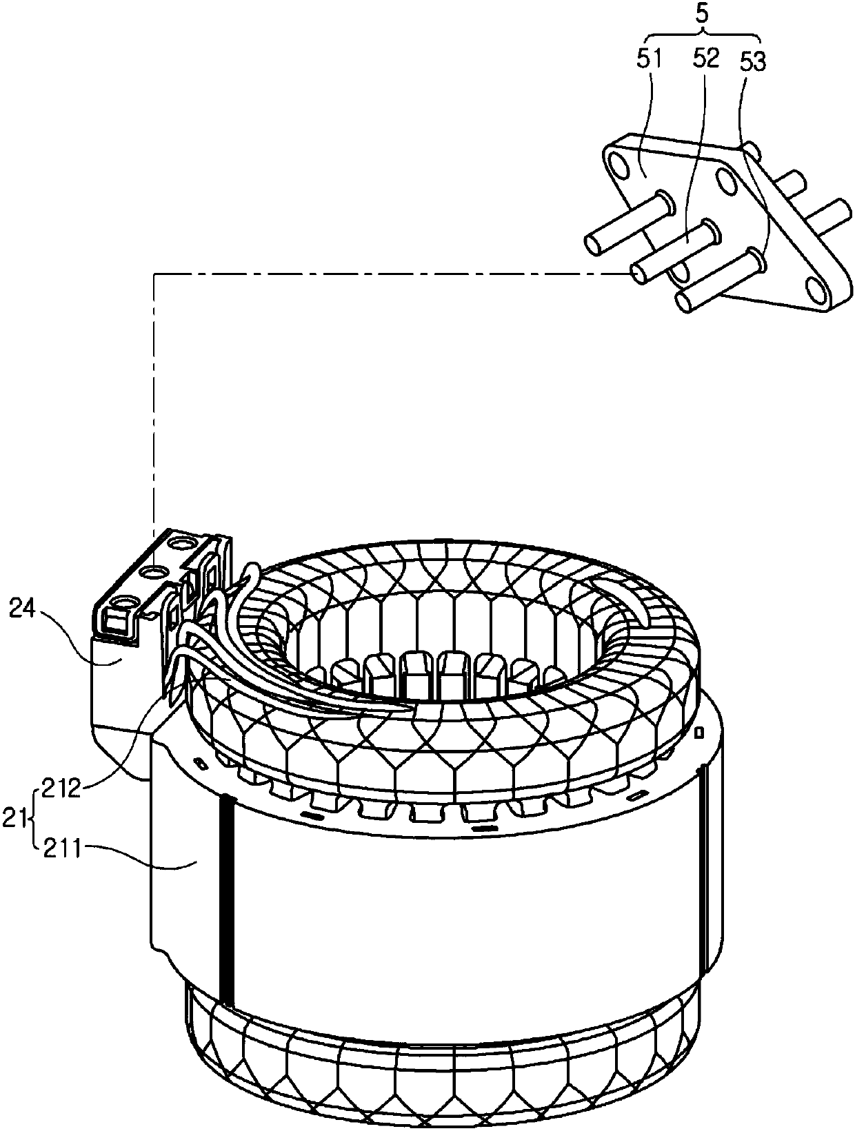
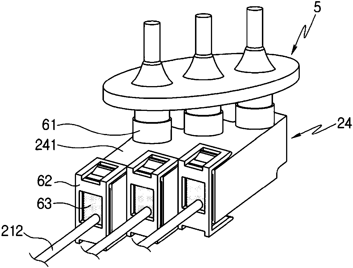
[0052] image 3 To show a perspective view of coils, terminals and connectors in a compressor according to an embodiment of the present invention, Figure 4 for image 3 The exploded perspective view of Figure 5 for image 3 cutaway view.

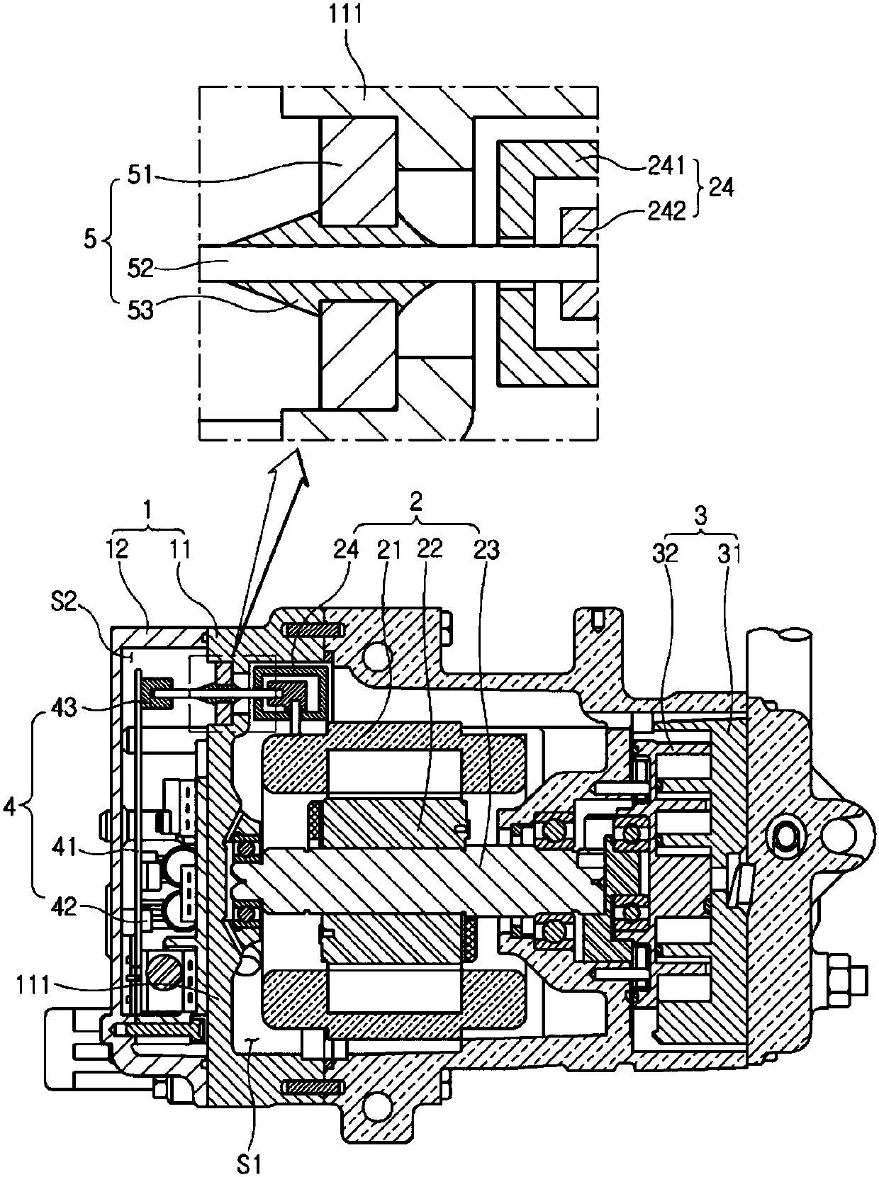
[0053] Refer to the attached Figure 3 to Figure 5 , the compressor in one embodiment of the present invention may include in the casing 1: a motor 2 for generating driving force; a compression mechanism 3 driven by the motor 2 for compressing the refrigerant; an inverter 4 , used to control the above-mentioned motor 2; the connector 5, used to electrically connect the above-mentioned motor 2 and the above-mentioned inverter 4; A leakage has occurred.

[0054] The above-mentioned casing 1 may include: a first casing 11, which accommodates the above-mentioned motor 2 and the above-mentioned compression mechanism 3; The abo...


PUM


Abstract

The present invention relates to a compressor comprising: a motor for generating a driving force; a compression mechanism driven by the motor so as to compress a refrigerant; an inverter for controlling the motor; a connector for electrically connecting the motor and the inverter; and a sealing member for sealing a motor terminal of the motor, electrically connected to the connector. Therefore, arefrigerant is prevented from flowing into a motor terminal, so that the occurrence of a short circuit in the motor terminal can be prevented. Further, it is possible to prevent a connector and a coilfrom being separated from the motor terminal.

Description

technical field [0001] The present invention relates to a compressor, and in more detail, relates to a compressor capable of compressing a refrigerant using a driving force of a motor controlled by an inverter. Background technique [0002] Generally, compressors used in automotive air-conditioning systems perform the function of sucking evaporated refrigerant from the evaporator, making it into a high-temperature, high-pressure state that facilitates liquefaction, and transferring it to the condenser. [0003] The above-mentioned compressors are classified into a method in which a driving force is received from an engine of a vehicle to perform a compression operation and a method in which a compression operation is performed by driving based on an electric motor (hereinafter, motor) powered by a separate power supply. [0004] figure 1 In order to show a sectional view of a conventional compressor that performs compression work by driving a motor, figure 2 to show figu...

Claims


Application Information

Patent Timeline
Patent Type & Authority Applications(China)
IPC IPC(8): F04C27/00F04B39/12H02K5/10H02K5/22B60H1/32F04B35/04
CPCF04B35/04F04B39/121F04C18/0215F04C27/008F04C2240/40F04C2240/803F04C2240/808H02K5/10H02K5/225F04B39/12
Inventor 许廷吉徐祯基田上真二徐奉均李卿在
Owner HANON SYST
Features
  • R&D
  • Intellectual Property
  • Life Sciences
  • Materials
  • Tech Scout
  • Unparalleled Data Quality
  • Higher Quality Content
  • 60% Fewer Hallucinations
Learn More