
Tourniquet Cuff and method for manufacturing same

A technology of cuff and longitudinal direction, which is applied in the field of manufacturing this kind of tourniquet cuff, can solve the problems of cover folds, garbage generation, unfavorable resource efficiency, and excess materials, etc.

Inactive Publication Date: 2018-02-23
ULRIKH GMBKH & KO KG
View PDF8 Cites 2 Cited by
  • Summary
  • Abstract
  • Description
  • Claims
  • Application Information

AI Technical Summary

Problems solved by technology

Here, due to the flexible textile structure of the cuff cover, there is the risk that wrinkles will develop in the cover
Creases occur especially when inflating the cuff, since the inner circumference becomes shorter than the outer circumference, thereby creating an excess of material which causes wrinkles
Furthermore, the tourniquet cuff known from US 2013 / 028 96 12 A1 can only be cleaned and sterilized insufficiently, and it is provided only for one-time use, which is disadvantageous in terms of waste generation and from the point of view of resource efficiency. Adverse

Method used


Image

  • Tourniquet Cuff and method for manufacturing same
  • Tourniquet Cuff and method for manufacturing same
  • Tourniquet Cuff and method for manufacturing same

Examples


Embodiment Construction

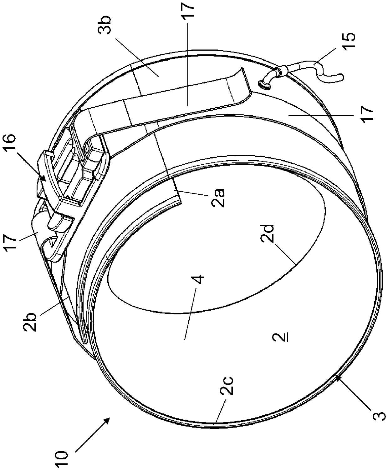
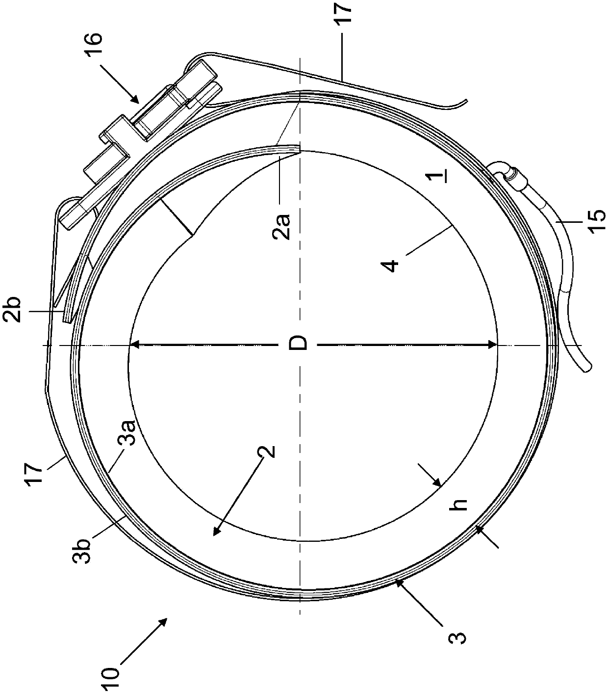
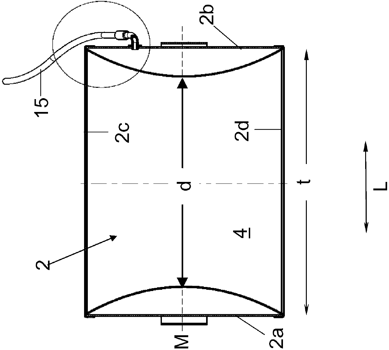
[0029] exist figure 1 and figure 2 A tourniquet cuff 10 according to the invention is shown for placement on a limb. The tourniquet 10 comprises an inflatable body 2 which surrounds an air-tight inflatable chamber 1 . The inflation body 2 can be connected to a compressed gas source (not shown here) via a line 15 connected to the inflation chamber 1 . The source of compressed gas can be, for example, a compressor which supplies compressed gas, in particular compressed air, with which the inflation body can be inflated. The pressure for inflating the inflation body 2 is controlled here via a control unit contained in the pressure source. Such a control unit for controlling a tourniquet cuff is known from the prior art. A closure strip 17 with a closure 16 is fastened on the outside of the inflatable body 2 . The closure strip 17 can be fixed in the desired position by means of the closure element 16 designed here as a snap button, in order to be able to secure the tourniqu...


PUM

PropertyMeasurementUnit
Elastic modulusaaaaaaaaaa
Shore hardnessaaaaaaaaaa

Abstract

A tourniquet cuff for placement on a limb, has an inflatable body 2 which encloses an inflatable chamber 1 and which can be inflated with a compressed gas so as to create blood flow restriction in thelimb, with the inflatable body 2 being formed from an elongated support 3 made of a bendable support material extending along a longitudinal direction and from a stretchable wall 4 made of a stretchable material attached to the support. In order to enable thorough and easy cleaning and sterilization of the tourniquet cuff and easy placement on a limb and to ensure the most uniform possible distribution of the pressure exerted by the tourniquet cuff on the limb, the stretchable wall is affixed to the elongated support while the stretchable material is stretched at least in the longitudinal direction. A method of manufacturing the tourniquet cuff is also disclosed.

Description

technical field [0001] The invention relates to a tourniquet cuff for placement on a limb and for achieving hemostasis in a limb, and a method for producing such a tourniquet cuff. Background technique [0002] Hemostatic devices in the form of inflatable cuffs are known from the prior art, for example from US Pat. The inflatable cuff is connected to a source of compressed gas for hemostasis in the limb, and is inflated with the compressed gas (or compressed air) so that the cuff exerts a pressure on the limb that is great enough to hold the limb, while being held by the cuff. The blood flow in the section surrounded by the band is at least largely or completely interrupted. Such hemostatic devices are used, for example, during surgery on limbs in which extensive or complete hemostasis or even bloodless areas in the operative field are produced and should be maintained during surgery in order to simplify surgery or reduce the vascular system. risk of damage. To inflate th...

Claims


Application Information

Patent Timeline
IPC IPC(8): A61B17/135
CPCA61B17/135A61B2017/00862A61B2017/00946A61B2017/00951A61B17/1322A61B2017/00526A61B2017/00831A61B2017/00955
Inventor 斯文·埃德曼乌韦·斯特里戈瓦萨拉·安德里亚·迪亚纳·温伯克
Owner ULRIKH GMBKH & KO KG
Learn More