
Travelling automatic fertilizing method

A fertilization method, walking technology, applied in the field of walking automatic fertilization, can solve the problems of low utilization rate of chemical fertilizers, low degree of automation, low efficiency, etc., and achieve the effect of convenient and uniform spreading, fast and efficient fertilization process

Inactive Publication Date: 2018-01-16
俞秋芳
View PDF0 Cites 0 Cited by
  • Summary
  • Abstract
  • Description
  • Claims
  • Application Information

AI Technical Summary

Problems solved by technology

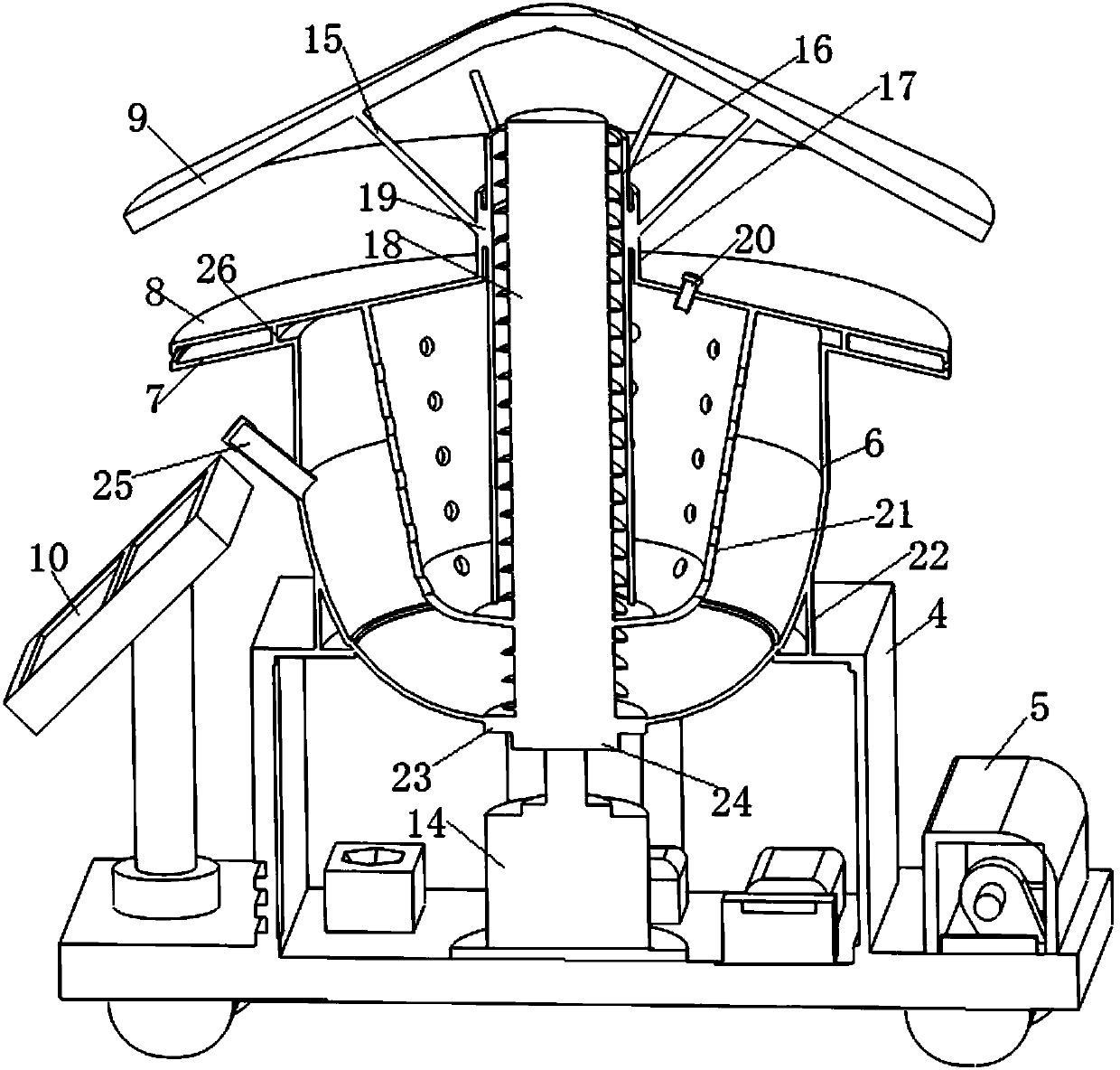
[0002] When the soil cannot provide the nutrients needed for crop growth and development, the act of artificially supplementing crops with nutrient elements is called fertilization, which can increase soil nutrients, whether using organic fertilizers or inorganic fertilizers, can increase soil nutrients and improve soil structure. Apply organic fertilizers and fertilizers rich in calcium to promote the formation of soil aggregate structure and improve soil water and heat conditions. Generally, organic matter has the ability to absorb and retain water, especially hydrocolloids such as humus, which have stronger water retention and increase Adding organic fertilizers with physiologically active substances can promote the activity of microorganisms. Traditional fertilization methods are labor-intensive and time-consuming, and the utilization rate of chemical fertilizers is not high, which can easily cause soil compaction and other phenomena. Some existing fertilization devices are either complex in structure, expensive, or The structure is single, the efficiency is low, and the degree of automation is low, so we need an efficient and economical fertilization device

Method used


Image

  • Travelling automatic fertilizing method
  • Travelling automatic fertilizing method
  • Travelling automatic fertilizing method

Examples


Embodiment Construction

[0012] The technical solutions in the embodiments of the invention will be clearly and completely described below in conjunction with the accompanying drawings in the embodiments of the invention. Obviously, the described embodiments are only part of the embodiments of the invention, not all of them. Based on the embodiments of the invention, all other embodiments obtained by persons of ordinary skill in the art without making creative efforts belong to the protection scope of the invention.

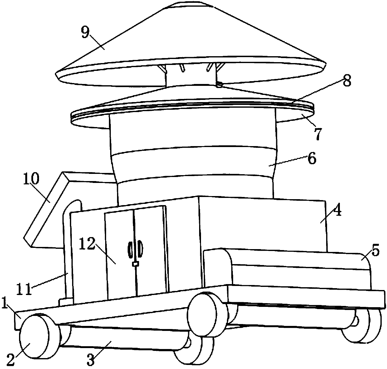
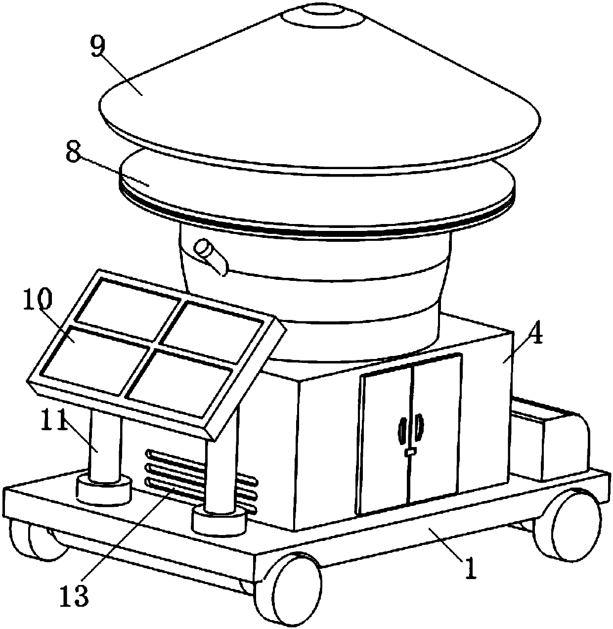
[0013] see Figure 1-4 , the invention provides a technical solution: the storage battery 30 provides electric energy, and when walking, the stepper motor 33 is excited by the driver 34 to continuously output a certain rotation angle, and its torque is output to the axle box 3 through the transmission box 35, and then the wheel 2 rolls , and the timing of the timing module 28 and the stepping movement of the stepping motor 33 can facilitate the movement distance determined by the micro-h...


PUM


Abstract

The invention discloses a travelling automatic fertilizing method, which comprises a vehicle board, a case is installed at the center of the top face of the vehicle board, a power case is arranged atone side of the top face of the vehicle board, a fertilizer external warehouse is arranged at the center of the top face of case, and the bottom of the fertilizer external warehouse is infundibular. Aservo motor is arranged at the center of the inside of the case, an output shaft of the servo motor is connected to a shaft coupling, and the other end of the shaft coupling is connected to a spiralconveying shaft. A fertilizer inner warehouse is arranged inside the fertilizer external warehouse, a spraying board is arranged at the upper side of the fertilizer external warehouse, a top cover isarranged above the spraying board, and a connection pipe is arranged at the center of the middle part of the top face of the spraying board. The fertilizer inner warehouse is internally provided witha conveying pipe, the distance of which and the external surface of the spiral conveying shaft is less than 10 mm. The periphery of the connection pipe is uniformly connected to a plurality of supportrods at slop angles of 60 degrees, and the other sides of the support rods are connected to the inside of the top cover. A fertilizer can be sprayed in a travelling manner, and the fertilizing is efficient and convenient.

Description

technical field [0001] The invention relates to the technical field of agricultural machinery, in particular to a walking automatic fertilization method. Background technique [0002] When the soil cannot provide the nutrients needed for crop growth and development, the act of artificially supplementing crops with nutrient elements is called fertilization, which can increase soil nutrients, whether using organic fertilizers or inorganic fertilizers, can increase soil nutrients and improve soil structure. Apply organic fertilizers and fertilizers rich in calcium to promote the formation of soil aggregate structure and improve soil water and heat conditions. Generally, organic matter has the ability to absorb and retain water, especially hydrocolloids such as humus, which have stronger water retention and increase Adding organic fertilizers with physiologically active substances can promote the activity of microorganisms. Traditional fertilization methods are labor-intensive a...

Claims


Application Information

Patent Timeline
Patent Type & Authority Applications(China)
IPC IPC(8): A01C15/12
Inventor 俞秋芳
Owner 俞秋芳
Learn More