
Punching machine propulsion alarming device

A technology of alarm device and stamping device, applied in the direction of press, metal processing equipment, safety equipment, etc., to prevent excessive stamping

Inactive Publication Date: 2018-02-23
天津普越金属制品有限公司
View PDF5 Cites 1 Cited by
  • Summary
  • Abstract
  • Description
  • Claims
  • Application Information

AI Technical Summary

Problems solved by technology

[0003] The purpose of the present invention is to provide a punching machine advance alarm device, which has the advantage of being able to prevent excessive punching during punching, and solves the problem that the punching work can be carried out better without damaging the components to be punched

Method used


Image

  • Punching machine propulsion alarming device
  • Punching machine propulsion alarming device
  • Punching machine propulsion alarming device

Examples


Embodiment Construction

[0019] The following will clearly and completely describe the technical solutions in the embodiments of the present invention with reference to the accompanying drawings in the embodiments of the present invention. Obviously, the described embodiments are only some, not all, embodiments of the present invention. Based on the embodiments of the present invention, all other embodiments obtained by persons of ordinary skill in the art without making creative efforts belong to the protection scope of the present invention.

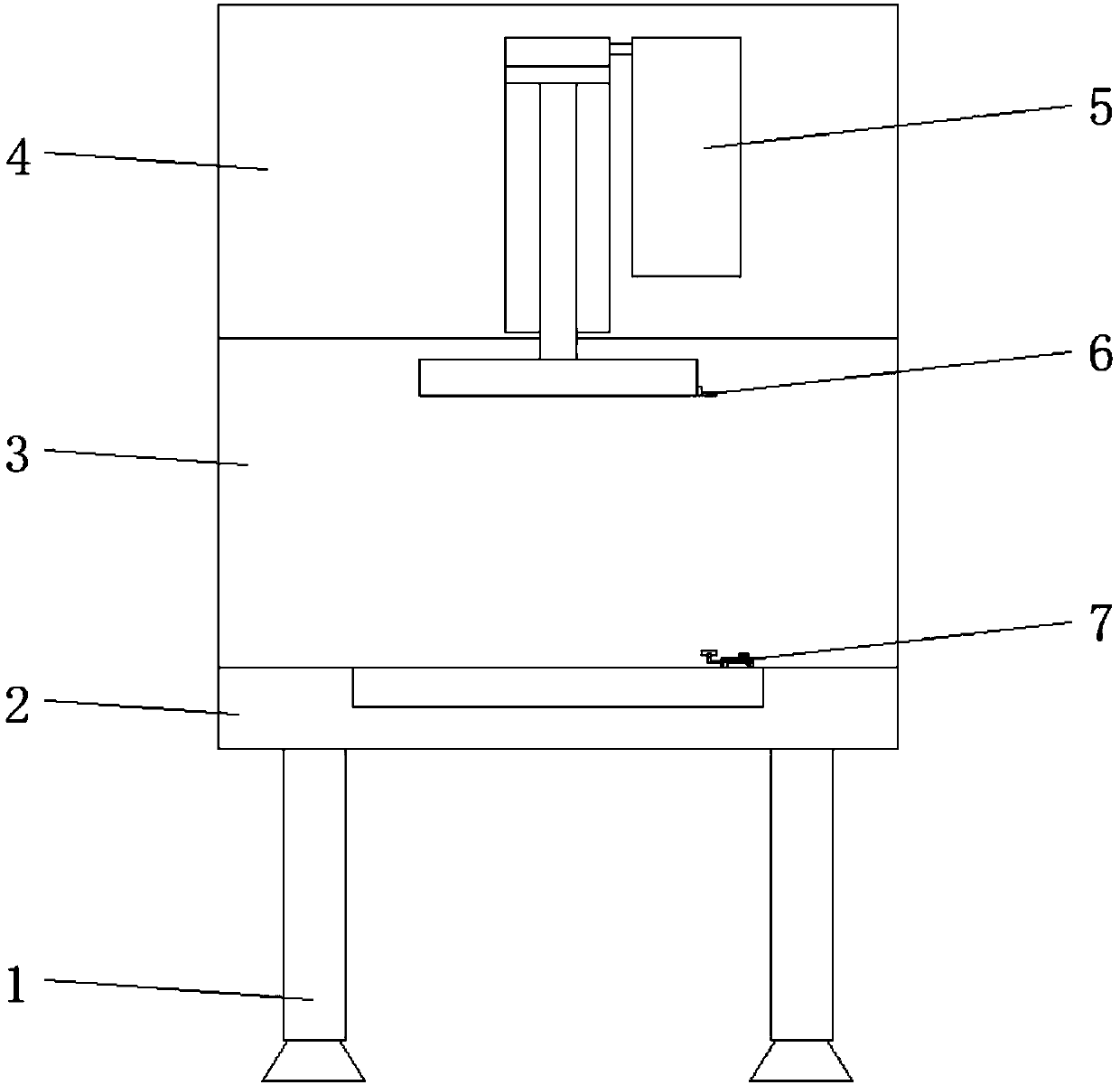
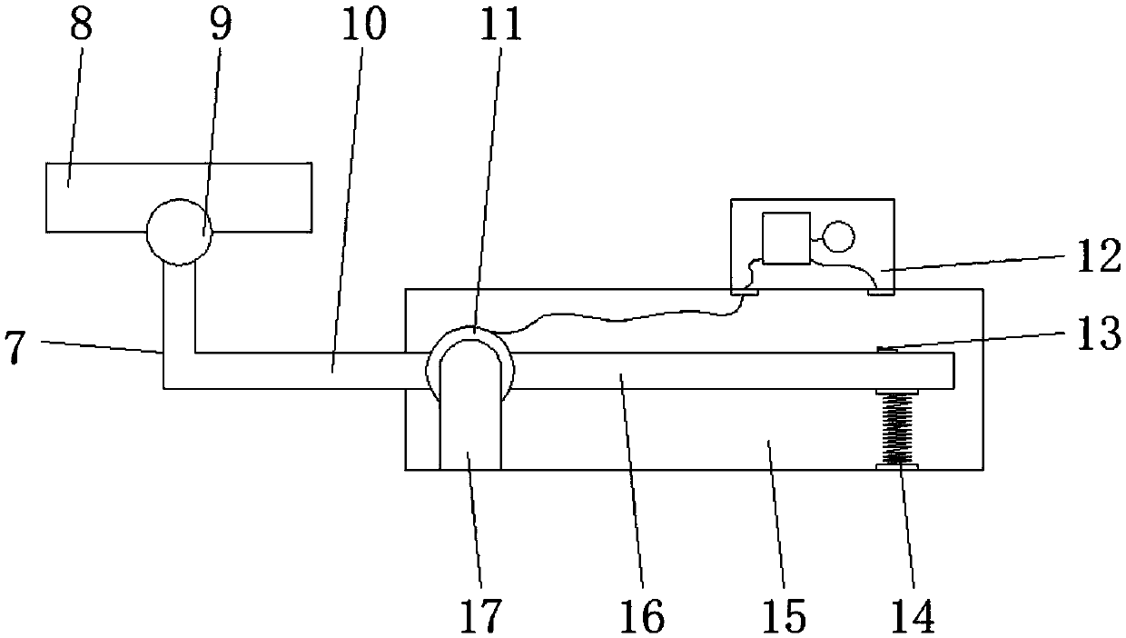
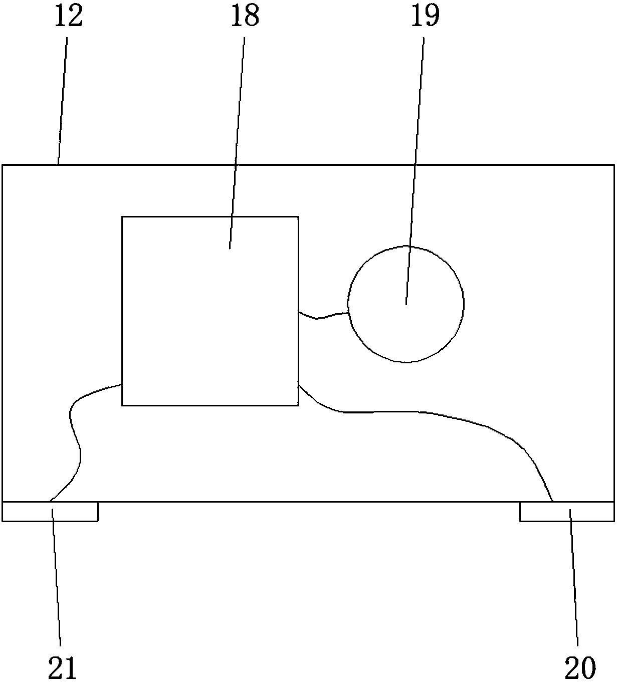
[0020] see Figures 1 to 3 , a kind of embodiment that the present invention provides: punching machine advances alarm device, comprises support column 1, installation plate 2, back plate 3, stamping box 4, stamping device 5 and alarm device 7, and support column 1 is welded on the lower end of installation plate 2 , there are four supporting columns 1, and the four supporting columns 1 are respectively arranged at the four corners of the lower end of the moun...


PUM


Abstract

The invention discloses a punching machine propulsion alarming device which comprises supporting columns, a mounting plate, a back plate, a punching box, a punching unit and an alarming unit. The supporting columns are welded to the lower end of the mounting plate. The back plate is mounted on the rear side of the upper end of the mounting plate. The punching box is mounted at the top end of the back plate. The punching unit is mounted in the punching box. The alarming unit is mounted on one side of the upper end of the mounting plate. An alarm apparatus box is arranged on the outer side of the lower end of the alarming unit. Shaft mounting plates are mounted on one side in the alarm apparatus box. The shaft mounting plates are connected through a rotating intermediate shaft. An L-shaped rotating bar is mounted on one side of the rotating intermediate shaft. A conductor rotating bar is mounted on the other side of the rotating intermediate shaft. An alarm apparatus is mounted on the upper surface of the end, away from the rotating intermediate shaft, of the alarm apparatus box. A storage battery box is mounted on one side in the alarm apparatus. The punching machine propulsion alarming device can be used for reminding working staff in a buzzer alarming mode when punching propulsion is performed, and excessive punching is prevented.

Description

technical field [0001] The invention relates to the technical field of punching machine mechanical equipment, in particular to a punching machine advance alarm device. Background technique [0002] The design principle is to convert circular motion into linear motion. The main motor drives the flywheel, and the clutch drives the gear, crankshaft, connecting rod, etc. to achieve the linear motion of the slider. The motion from the main motor to the connecting rod is circular motion. , There must be a transfer point between circular motion and linear motion between the connecting rod and the slider. There are roughly two mechanisms in its design, one is a ball type, and the other is a pin type. Through this mechanism, the circular motion is converted into sliding motion. The linear movement of the block, the strength of the punching machine is very large, but the stroke of the punching is not convenient to be controlled. If the punching is excessive, it will cause damage to th...

Claims


Application Information

Patent Timeline
Patent Type & Authority Applications(China)
IPC IPC(8): B21D55/00B30B15/14
CPCB21D55/00B30B15/148
Inventor 河元福
Owner 天津普越金属制品有限公司
Learn More