
Temperature correcting mold for spark plasma sintering

A discharge plasma and mold technology, which is applied in the field of temperature calibration molds, can solve the problems of sample melting, temperature measurement errors, and increased experimental costs.

Active Publication Date: 2018-02-23
苏州匀晶金属科技有限公司
View PDF8 Cites 4 Cited by
  • Summary
  • Abstract
  • Description
  • Claims
  • Application Information

AI Technical Summary

Problems solved by technology

Therefore, there is a considerable error in its temperature measurement, which seriously affects the preparation of the pattern, and when the metal with a low melting point is sintered, it will also cause the melting of the sample, which will damage the spark plasma sintering equipment, causing unnecessary losses and increasing the cost of the experiment.

Method used


Image

  • Temperature correcting mold for spark plasma sintering
  • Temperature correcting mold for spark plasma sintering

Examples


Embodiment Construction

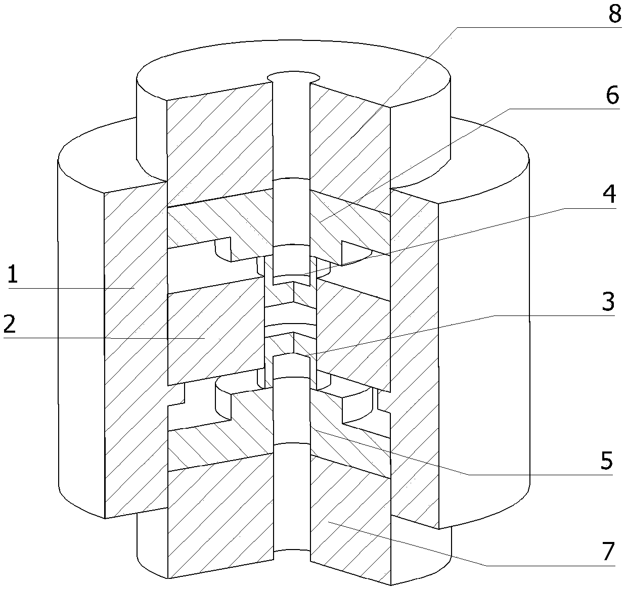
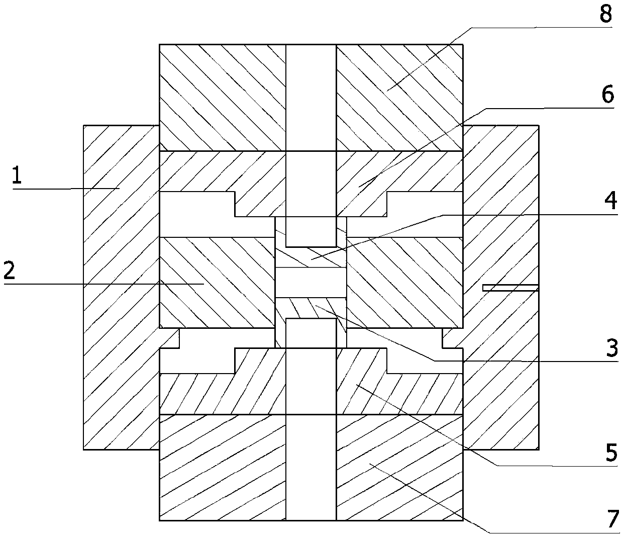
[0021] This embodiment is a temperature calibration mold for spark plasma sintering. The prepared nanocrystalline powder is placed in the sintering area formed by the inner mold, the upper inner pressure head and the lower inner pressure head to ensure that the powder is tightly packed in the sintering area. When working, place the whole set of molds in the discharge plasma sintering equipment, turn on the thermocouple temperature measurement and infrared temperature measurement at the same time, and turn on the electricity to make the whole mold heated up evenly, and at the same time, the pressure acts on the outer pressure head. The block is pushed to move to the inside of the mold, the force is transmitted through the steps, and finally the pressure is applied to the powder sample, so that the powder sample is sintered under pressure. Observe the temperature measured by infrared rays and thermocouples during the sintering process. When the temperature measured by infrared r...


PUM


Abstract

The invention discloses a temperature correcting mold for spark plasma sintering. The temperature correcting mold is composed of an outer mold, an inner mold, a lower outer pressure head, an upper outer pressure head, a lower cushion block, an upper cushion block, an upper inner pressure head and a lower inner pressure head; the outer mold is a hollow cavity with openings in the upper end and thelower end, and the inner mold is embedded in the outer mold and is located on a side wall baffle block; the upper inner pressure head, the upper cushion block and the upper outer pressure head are located above the inner mold, and an axial through hole is formed in the middle of the upper cushion block and the middle of the upper outer pressure head and communicates with a middle groove in the upper inner pressure head; the lower inner pressure head, the lower cushion block and the lower outer pressure head are located below the inner mold, and an an axial through hole is formed in the middleof the lower cushion block and the middle of the lower outer pressure head and communicates with a middle groove in the lower inner pressure head; the upper through hole and the lower through hole areused as a light path channel for infrared temperature measurement; and a blind hole is formed in the wall of the outer mold and is used for installing a thermocouple to monitor the temperature in real time. The temperature measurement of the thermocouple is calibrated by adopting infrared temperature measurement, a sintering pattern is ensured to be at the same sintering temperature in the sintering process, the experiment precision is improved, and the operation risk of equipment is reduced.

Description

technical field [0001] The invention relates to the technical field of powder metallurgy sintering equipment, in particular to a temperature calibration mold for spark plasma sintering. Background technique [0002] In the field of material science research, nanocrystalline materials have triggered a research boom at home and abroad because of their excellent properties. However, due to limited preparation technology, it is currently difficult to prepare large nanocrystalline bulk materials. In contrast, the technology of preparing nanocrystalline powder by high-energy ball milling is relatively mature, so the preparation of powder into bulk nanocrystalline materials by powder metallurgy has become a current research hotspot. Nanocrystalline materials are sensitive to temperature, and will spontaneously grow at a certain temperature, thus becoming ultra-fine or even coarse-grained materials, and losing their excellent properties. Therefore, precise control of temperature du...

Claims


Application Information

Patent Timeline
IPC IPC(8): B22F3/105B22F3/03
CPCB22F3/03B22F3/105B22F2202/13B22F2203/11
Inventor 陈豫增单贵斌宫明明张文祥董浩刘峰
Owner 苏州匀晶金属科技有限公司
Learn More