Electric car wheel-side reducer assembly structure and control method thereof

A technology for the wheel and assembly structure of electric vehicles, applied in the direction of control devices, motion deposition, power devices, etc., can solve problems such as inability to accurately control the driving force, and achieve improved vehicle passing performance, high transmission efficiency, and improved power transmission efficiency effect

Inactive Publication Date: 2018-02-23
杭州伯坦科技工程有限公司
View PDF7 Cites 1 Cited by
  • Summary
  • Abstract
  • Description
  • Claims
  • Application Information

AI Technical Summary

Problems solved by technology

Because there is only a single power source, the power distribution basically depends on the mech...

Method used


Image

  • Electric car wheel-side reducer assembly structure and control method thereof
  • Electric car wheel-side reducer assembly structure and control method thereof
  • Electric car wheel-side reducer assembly structure and control method thereof

Examples


Embodiment

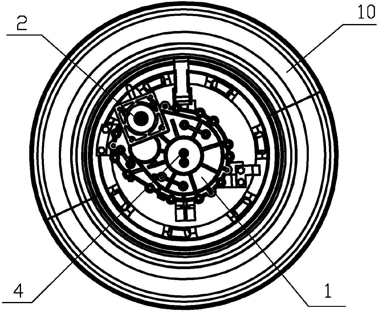
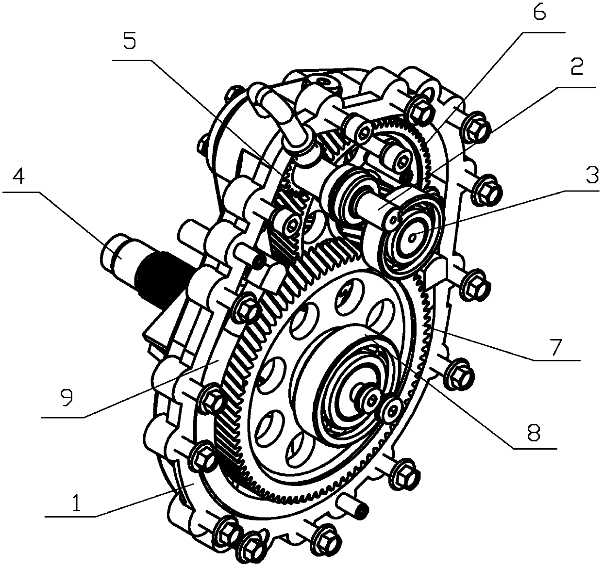
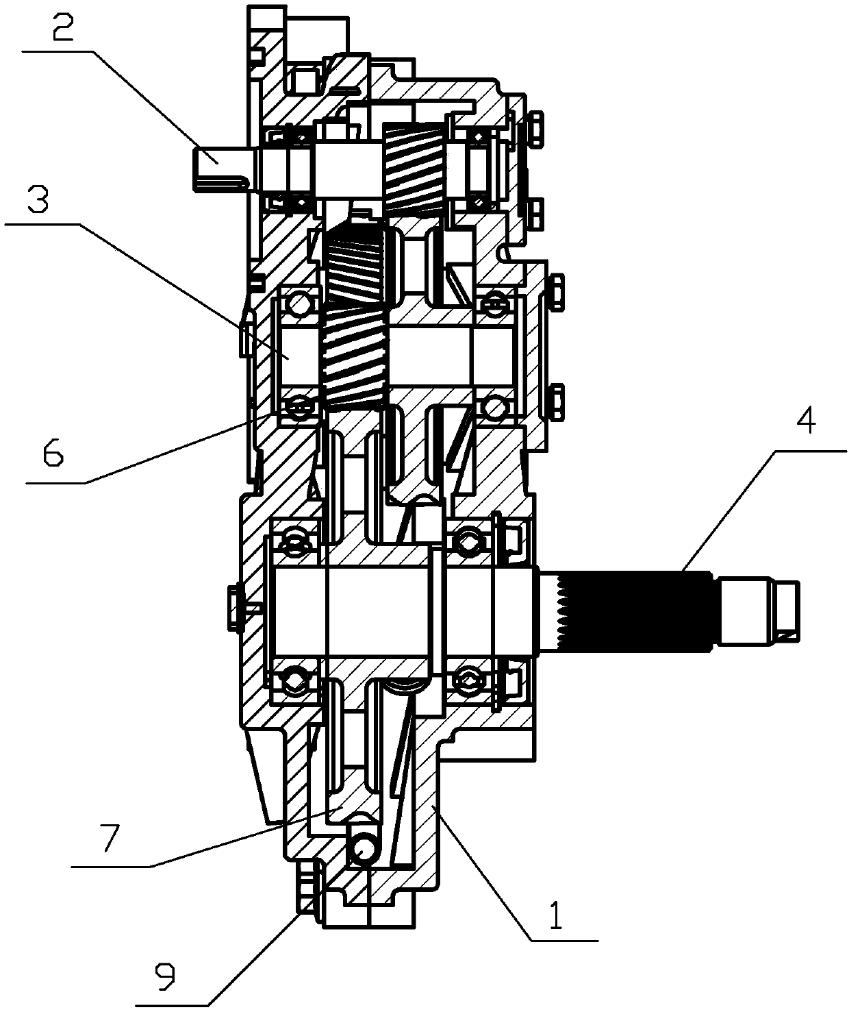
[0018] Example: The structure of the wheel reducer assembly of the electric vehicle in this example is as follows: figure 1 , figure 2 , image 3 As shown, it includes a box body 1 and an input shaft 2, an intermediate shaft 3 and an output shaft 4 installed in the box body 1. The box body is formed by connecting the front side box body and the rear side box body, and one end of the input shaft 2 protrudes out. In the front case, one end of the output shaft 4 protrudes from the rear case, the input shaft 2, the intermediate shaft 3 and the output shaft 4 are distributed in a triangular structure, the distance between the input shaft 2 and the output shaft 4 is 120mm, and the input shaft 2 An input gear 5 is installed on it, an intermediate gear 6 is installed on the intermediate shaft 3, and an output gear 7 is installed on the output shaft 4. The input gear 5 and the output gear 7 mesh with the intermediate gear 6 respectively. The input gear 5, the output gear 7 and the in...


PUM


Abstract

The invention relates to an electric car wheel-side reducer assembly structure and a control method thereof. The electric car wheel-side reducer assembly structure comprises an input shaft, an input gear, an intermediate shaft, an intermediate gear, an output shaft and an output gear which are arranged in a box, wherein the input shaft, the intermediate shaft and the output shaft are distributed in a triangular structure, the input gear and the output gear are meshed with the intermediate gear separately, the input shaft is connected with a wheel-side motor arranged beside a wheel of an electric car through a coupling, and the output shaft is connected with the hub of the wheel of the electric car through a male spline. When the wheel-side motor runs, torque is transmitted to the input shaft, after overall torque speed reduction from the input gear to the intermediate gear to the output gear, the torque is transmitted to the output shaft, and finally the output shaft drives the wheel of the electric car, so that the electric car runs. The electric car wheel-side reducer assembly structure is high in transmission efficiency and capable of precisely controlling the driving force of each wheel; as the structure occupies a small space, a large interior space of the car can be achieved, and as the vehicle ground clearance is large, the vehicle passage capacity can be improved.

Description

technical field [0001] The invention relates to the field of electric vehicle manufacturing, in particular to a wheel reducer assembly structure of an electric vehicle and a control method thereof. Background technique [0002] Due to the need for energy saving and emission reduction, electric vehicles are becoming more and more popular. At present, the driving method of automobiles still uses a single engine or a single electric motor to provide a power source, which is transmitted to each driving wheel of the automobile through a mechanical transmission system. Because there is only a single power source, the power distribution basically depends on the mechanical transmission mechanism, so the driving force of each wheel cannot be precisely controlled. With the increasing popularity of electric vehicles, the requirements for the power transmission efficiency of electric vehicles are getting higher and higher. In order to meet the comfort of riding, it is necessary to have...

Claims


Application Information

Patent Timeline
IPC IPC(8): B60K7/00B60K17/12F16H57/023
CPCB60K7/00B60K17/12F16H57/023
Inventor 聂亮朱国方罗勇厉蒋
Owner 杭州伯坦科技工程有限公司
Why Eureka
Try Eureka