A traction elevator with controllable airflow

A traction and elevator technology, applied in the field of traction elevators, can solve problems such as poor breathing of passengers, hot car, shock, etc., and achieve the effects of avoiding finger slippage, improving comfort, and increasing contact area.

Active Publication Date: 2019-03-12
苏迅电梯有限公司
View PDF6 Cites 0 Cited by
  • Summary
  • Abstract
  • Description
  • Claims
  • Application Information

AI Technical Summary

Problems solved by technology

[0002] Traction elevators are widely used in large commercial buildings, office buildings and other areas as people's interlayer transportation equipment. However, the load capacity of traction elevators is a fixed value, and the passenger flow in shopping malls and other buildings has high and low peaks. When the office building encounters the off-duty rush hour or the shopping mall encounters holidays, there will be more passengers taking the traction elevator than usual. At this time, the air flow in the small traction elevator car is not smooth, which will cause The inside of the car is getting hotter and hotter, which can easily cause the passengers in the car to suffer from shortness of breath or even fainting and shock.

Method used


Image

  • A traction elevator with controllable airflow
  • A traction elevator with controllable airflow
  • A traction elevator with controllable airflow

Examples


Embodiment 1

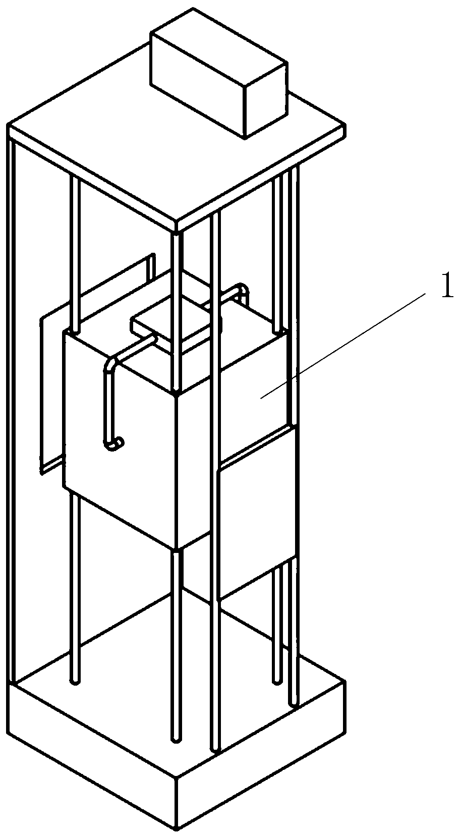
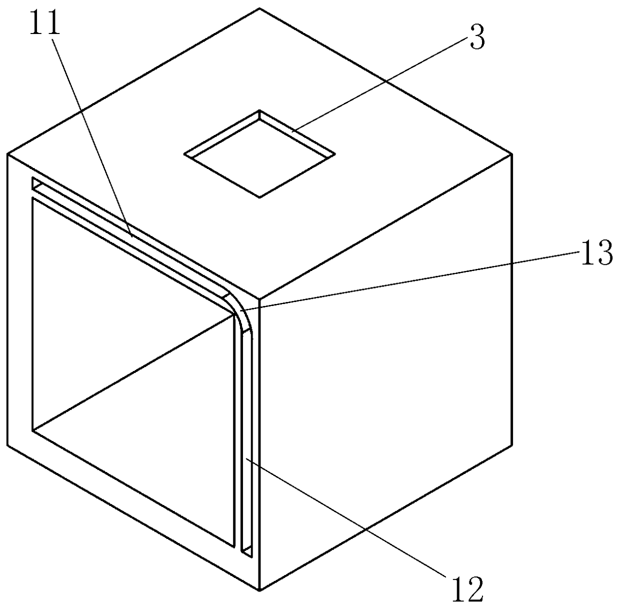
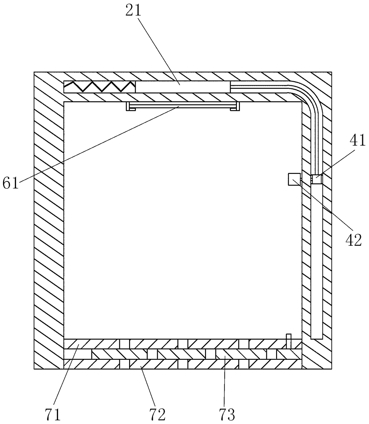
[0033] Example 1, such as figure 1 Shown is an overall schematic diagram of a traction elevator with controllable airflow. A traction elevator with controllable airflow, comprising a car 1, a wire rope, a counterweight and a traction machine, wherein, such as figure 2As shown, the car 1 includes a car top surface, a car side surface and a car bottom surface. The car top surface includes a headspace groove 11. The headspace groove 11 is a rectangular parallelepiped hollow groove extending in the horizontal direction. The slot 12 is a rectangular parallelepiped hollow slot extending in the vertical direction. The headspace slot 11 and the side slot 12 are connected by a connecting slot 13. There is an opening and closing plate 21 in the headspace slot 11, and the opening and closing plate 21 is connected to the headspace slot through elastic connectors. 11 is connected to the end face away from the side of the connecting groove 13. There is a push part in the side cavity 12. T...


PUM


Abstract

The invention relates to the field of elevator manufacturing, in particular to an airflow controllable traction elevator. The airflow controllable traction elevator comprises a car, steel wire ropes,a counter weight and a traction machine. The car comprises a car top face, a car side face and a car bottom face. The car top face comprises a top empty groove. The car side face comprises a side empty groove. The top empty groove is connected with the side empty groove through a connecting groove. An opening and closing plate is arranged in the top empty groove and is connected with the end faceof the side, away from the connecting groove, of the top empty groove through an elastic connecting part. A pushing portion is arranged in the side empty groove. The opening and closing plate and thepushing portion are connected through a bendable supporting rod. A vertical moving groove is formed in the inner surface of the car side face and is a vertical strip groove communicating the inner space of the car with the side empty groove. A ventilation portion is further arranged on the car top face. Ventilation controllability of the car is improved, the car has better inner and outer air flowability when receiving a large number of passengers, and the personal safety problem generated by poor ventilation in the car is avoided.

Description

technical field [0001] The invention relates to the field of elevator manufacturing, in particular to a traction elevator with controllable air flow. Background technique [0002] Traction elevators are widely used in large commercial buildings, office buildings and other areas as people's interlayer transportation equipment. However, the load capacity of traction elevators is a fixed value, and the passenger flow in shopping malls and other buildings has high and low peaks. When the office building encounters the off-duty rush hour or the shopping mall encounters holidays, there will be more passengers taking the traction elevator than usual. At this time, the air flow in the small traction elevator car is not smooth, which will cause The inside of the car is becoming more and more stuffy, which is likely to cause the passengers in the car to suffer from shortness of breath or even faint and shock. Contents of the invention [0003] The purpose of the present invention i...

Claims


Application Information

Patent Timeline
Patent Type & Authority Patents(China)
IPC IPC(8): B66B11/02
CPCB66B11/024
Inventor 卢建纯冯斌余寿祥
Owner 苏迅电梯有限公司
Why Eureka
Try Eureka