
Mechanical traction manufacturing device

A technology for manufacturing devices and mechanical traction, applied in the directions of transportation and packaging, load hanging components, etc., can solve problems such as wire rope damage, and achieve the effect of improving service life, good moving effect and long service time

Inactive Publication Date: 2018-02-23
褚圣海
View PDF0 Cites 6 Cited by
  • Summary
  • Abstract
  • Description
  • Claims
  • Application Information

AI Technical Summary

Problems solved by technology

[0003] The purpose of the present invention is to provide a mechanical traction manufacturing device, which has the advantage of adjusting the angle difference between the traction device and the steel wire rope, and solves the problem that the steel wire rope is damaged during use

Method used


Image

  • Mechanical traction manufacturing device
  • Mechanical traction manufacturing device
  • Mechanical traction manufacturing device

Examples


Embodiment Construction

[0017] The technical solutions in the embodiments of the present invention will be clearly and completely described below in conjunction with the accompanying drawings in the embodiments of the present invention. Obviously, the described embodiments are only part of the embodiments of the present invention, not all of them. Based on the embodiments of the present invention, all other embodiments obtained by persons of ordinary skill in the art without making creative efforts belong to the protection scope of the present invention.

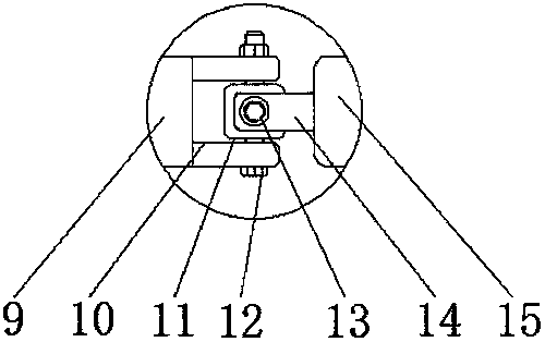
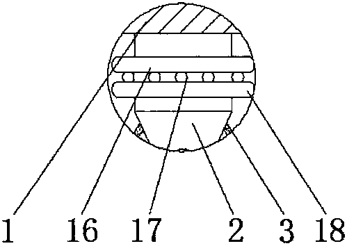
[0018] see Figure 1-4 , a mechanical traction manufacturing device, comprising a traction plate 1, roller bearings 4 are provided through both sides of the traction plate 1, the inner surface of the roller bearing 4 is movably connected with a rotating shaft 5, and the outer side of the rotating shaft 5 is fixedly connected with a first rotating shaft 9 , the top and bottom outside the first rotating shaft 9 are provided with a first connecting pl...


PUM


Abstract

The invention discloses a mechanical traction manufacturing device which comprises a traction plate. Roller bearings are arranged on the two sides of the traction plate in a penetrating mode, and theinner surfaces of the roller bearings are movably connected with a rotary shaft; the outer side of the rotary shaft is fixedly connected with a first rotary shaft, and first connecting plates are arranged at the top and the bottom of the outer side of the first rotary shaft; and first bolts are arranged at the bottoms of the first connecting plates, and one ends of the first bolts penetrate through the first connecting plates. According to the mechanical traction manufacturing device, through cooperative use of the roller bearings, the rotary shaft, the first rotary shaft, the first connectingplates, a movable block, the first bolts, second bolts, second connecting plates, a second rotary shaft and a through hole, the angle adjusting effect can be achieved on a steel wire rope, thus the use effect of a traction device is better, and the problem that in the process that the traction device conducts traction on a mechanical device, due to adjusting of the moving direction of the traction device, the angle difference is generated between the traction device and the steel wire rope is solved.

Description

technical field [0001] The invention relates to the technical field of mechanical manufacturing, in particular to a mechanical traction manufacturing device. Background technique [0002] With the development of science and technology, the traction device has been widely used in the manufacturing process of mechanical equipment. However, in the process of using the existing traction device on the market, the angle between the traction device and the wire rope cannot be adjusted during the steering process. Poor adjustments, which lead to the problem of damage to the wire rope during use, so that the traction device cannot work effectively in time, wasting a lot of time, and also reduced the service life of the wire rope and increased the use cost of the traction device . Contents of the invention [0003] The purpose of the present invention is to provide a mechanical traction manufacturing device, which has the advantage of adjusting the angle difference between the trac...

Claims


Application Information

Patent Timeline
Patent Type & Authority Applications(China)
IPC IPC(8): B66C1/12
CPCB66C1/122
Inventor 褚圣海
Owner 褚圣海
Learn More