Meal taking cabinet

A technology for taking dining cabinets and auxiliary cabinets, which is applied in the field of taking dining cabinets

Inactive Publication Date: 2018-02-23
苏州市睿虞电子科技有限公司
View PDF9 Cites 12 Cited by
  • Summary
  • Abstract
  • Description
  • Claims
  • Application Information

AI Technical Summary

Problems solved by technology

[0002] With the increasingly fierce market competition, people's pace of life is also showing a trend of accelerating, followed by the vigorous development of fast food and takeaway industries. When faced with a large number of food orders, if the customer does not pick up the food in time, the counter will soon show a tendency to pile up like a mountain, especially for some fast food restaurants with a large volume of take-out business, sometimes even in just ten minutes. Dozens of large orders are a huge challenge for the waiters and catering staff of the store. On the one hand, they need to follow up the customers corresponding to the orders in a timely manner; Another aspect of the experience of diners is to take into account the efficiency and accuracy of the delivery staff. Compared with the traditional ordering mode in the past, the new mode of placing orders through online APP undoubtedly makes the current fast food restaurants need to Innovate and break through the work of fast food delivery

Method used


Image

  • Meal taking cabinet
  • Meal taking cabinet
  • Meal taking cabinet

Examples


Embodiment Construction

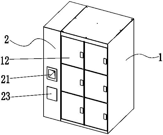
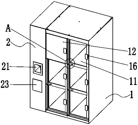
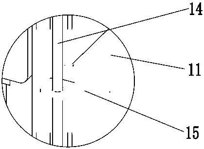
[0030] like Figures 1 to 4 As shown in one, the dining cabinet of the present invention includes a control cabinet 2 loaded with a controller (not shown) and an auxiliary cabinet 1 arranged side by side with the control cabinet 2, and the auxiliary cabinet 1 is separately arranged with several Meal storage compartment 11, said meal storage compartment 11 runs through the front and rear sides of the auxiliary cabinet 1, said meal storage compartment 11 is located at the side of the opening on the front side of the auxiliary cabinet 1 and is hinged with a cabinet door 12 for opening and closing the meal storage compartment , the other side of the cabinet door 12 opposite to its hinged side is provided with a lock 16 that is matched with the meal storage compartment 11, and the lock 16 is an electronically controlled lock that is opened by a controller. The control cabinet 2 A first scanner 21 is fixed on the front side on the same side as the cabinet door 12, a second scanner 2...


PUM


Abstract

The invention discloses a meal taking cabinet. The meal taking cabinet comprises a control cabinet and an auxiliary cabinet and is characterized in that the control cabinet is provided with a controller, the control cabinet and the auxiliary cabinet are parallelly arranged, the auxiliary cabinet is provided with a plurality of separated meal storage cells, a cell door for opening and closing eachmeal storage cell is hinged to one side of the opening, located on the front side of the auxiliary cabinet, of the meal storage cell, the other side, opposite to the hinged side, of each cell door isprovided with a lock cooperatively connected with the corresponding meal storage cell, each lock is an electric control lock and can be unlocked under the control of the controller, a first scanner isfixed on the front side, on the same side of the cell doors, of the control cabinet, a second scanner is fixed on the rear side, opposite to the front side, of the control cabinet, the first scannerand the second scanner are connected with the controller and controlled by the same, and an LED lamp electrically connected with the controller is arranged in each meal storage cell. By using the mealtaking cabinet, revenue can be increased while customer dining experience can be improved and popularity among consumers can be increased, fast food delivery efficiency is increased, the working efficiency of attendants is increased, time waste is reduced, and workload is lowered indirectly.

Description

technical field [0001] The invention relates to the field of item transfer devices, in particular to a dining cabinet. Background technique [0002] With the increasingly fierce market competition, people's pace of life is also showing a trend of accelerating, followed by the vigorous development of fast food and takeaway industries. When faced with a large number of food orders, if the customer does not pick up the food in time, the counter will soon show a tendency to pile up like a mountain, especially for some fast food restaurants with a large volume of take-out business, sometimes even in just ten minutes. Dozens of large orders are a huge challenge for the waiters and catering staff of the store. On the one hand, they need to follow up the customers corresponding to the orders in a timely manner; Another aspect of the experience of diners is to take into account the efficiency and accuracy of the delivery staff. Compared with the traditional ordering mode in the past...

Claims


Application Information

Patent Timeline
Patent Type & Authority Applications(China)
IPC IPC(8): G07F17/12G07C9/00G06Q50/12
CPCG06Q50/12G07C9/00571G07F17/12
Inventor 肖克
Owner 苏州市睿虞电子科技有限公司
Why Eureka
Try Eureka