
An assembly method for improving the metering accuracy of a membrane gas meter

A membrane gas meter and measurement accuracy technology, which is applied in the direction of volume measurement, measuring devices, assembly machines, etc., can solve problems such as unstable operation, inability to rotate with the crank, poor continuity of crank rotation, etc.

Active Publication Date: 2021-01-26
QIANWEI KROMSCHRODER METERS CHONGQING
View PDF10 Cites 0 Cited by
  • Summary
  • Abstract
  • Description
  • Claims
  • Application Information

AI Technical Summary

Problems solved by technology

The disadvantage of this technical solution is that during the assembly process of the rocker arm, the relative positioning between the rocker arm and the vertical shaft (and the folded plate fixedly installed at the bottom) is not considered, so due to the pressure resistance or shaking, the rocker arm and the There will be a slight offset that is difficult to detect between the vertical shafts (it will change the angle or relative position between the fixed folding plate at the lower end of the vertical shaft and the rocker arm), resulting in the limit position of the gas meter diaphragm running (touching the wall of the metering gas chamber) Does not correspond to the dead point position of the crank (the dead point position is the position where the connecting rod exerts zero rotational torque on the crankshaft)
In this way, there will be a situation that "after the diaphragm reaches the limit position and moves in reverse, the crank cannot rotate with it", which will cause poor continuity of crank rotation, unstable operation, and a decrease in measurement accuracy.

Method used

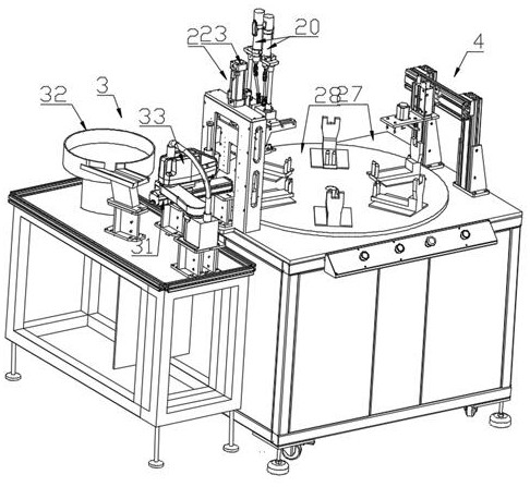
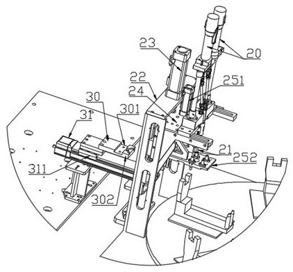
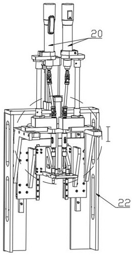

Image

  • An assembly method for improving the metering accuracy of a membrane gas meter
  • An assembly method for improving the metering accuracy of a membrane gas meter
  • An assembly method for improving the metering accuracy of a membrane gas meter

Examples


Embodiment Construction

[0033] The present invention will be further described in detail below in conjunction with the accompanying drawings.

[0034] An assembly method for improving the metering accuracy of a membrane gas meter, comprising the following steps:

[0035] a. Double rocker arm positioning:

[0036] Keep the two rocker arms overlapping vertically and form a symmetrical X-shaped cross in the direction of top view;

[0037] b. Double rocker arm pressing:

[0038] Press-fit the sleeve 101 for connecting the vertical shaft on the double rocker arm in step a to the knurled section at the top of the double vertical shaft 11;

[0039] Also include step c done before step b:

[0040] c. Double vertical shaft 11 rotation positioning:

[0041] After the double vertical shafts 11 are rotated to synchronously drive the flaps, diaphragms and diaphragms to move, the diaphragms in each metering box 12 are positioned at the center line of the metering box 12 in the thickness direction to realize th...


PUM


Abstract

The invention discloses an assembling method for improving metering precision of a diaphragm type gas meter. The assembling method comprises the following steps that a, double rocker arms are positioned, specifically, the two rocker arms are kept vertically overlapped and in a left-right symmetrical X-shaped cross shape in a top-down direction; and b, the double rocker arms are subjected to pressfitting, specifically, connecting vertical shafts on the double rocker arms in the a step are subjected to press fitting to knurled sections at the tops of double vertical shafts by using sleeves, andthe assembling method is characterized by further comprising a step c completed before the step b, wherein in the step c, the double vertical shafts are rotated and positioned, specifically, after afolding plate, a diaphragm plate and diaphragms are synchronously driven to act through rotation of the double vertical shafts, the diaphragms in all metering boxes are enabled to be positioned in center lines in the thickness direction of the metering boxes so as to realize dual vertical shaft positioning. The assembling method for improving the metering precision of the diaphragm type gas metercan help to improve the metering precision of the diaphragm type gas meter.

Description

technical field [0001] The invention belongs to the field of membrane gas meters, and in particular relates to an assembly method for improving the measurement accuracy of a membrane gas meter. Background technique [0002] The diaphragm gas meter is mainly composed of a metering part (including two metering boxes with flexible diaphragms inside each), a transmission part (including a diaphragm, a folding plate, a vertical shaft, a rocker arm, a connecting rod, a crank, a shift fork and a valve cover) ), the counting part and the housing, wherein, except for the housing, the remaining parts are collectively referred to as the movement of the diaphragm gas meter. The patent documents of CN201273832Y and CN201463953U promptly show the structure of membrane gas meter. [0003] The working principle of the membrane gas meter is: a diaphragm (usually made of synthetic rubber) is sealed at the center line of each metering box, and the diaphragm divides the inside of the metering ...

Claims


Application Information

Patent Timeline
Patent Type & Authority Patents(China)
IPC IPC(8): B23P21/00G01F1/38G01F15/16
CPCB23P21/006G01F1/38G01F15/16
Inventor 寇明林曾勇周强刘春建肖楠吕东红陈又
Owner QIANWEI KROMSCHRODER METERS CHONGQING
Learn More