Plug-in type insulation sleeve
An insulating sleeve and plug-in technology, applied in the direction of insulators, insulators, electrical components, etc., can solve the problems of limited length of insulating sleeve, affect work efficiency, time-consuming connection, etc., achieve good elasticity and flexibility, and prolong service life , to achieve the effect of a stable connection
- Summary
- Abstract
- Description
- Claims
- Application Information
AI Technical Summary
Problems solved by technology
Method used
Image
Examples
Embodiment 1
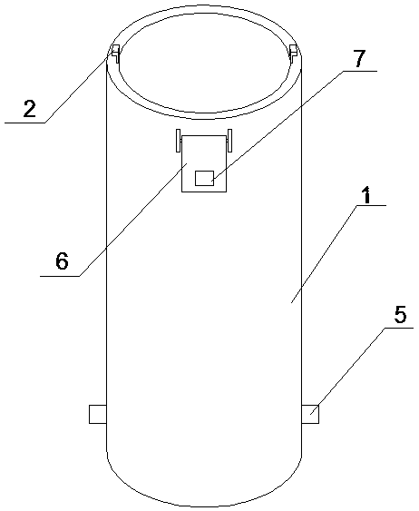
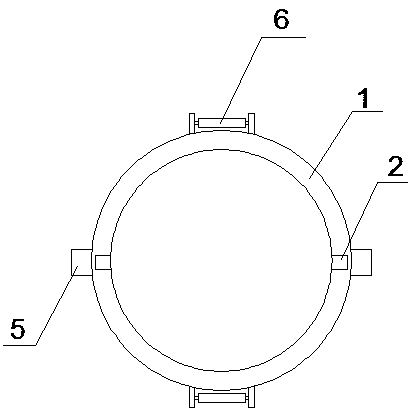
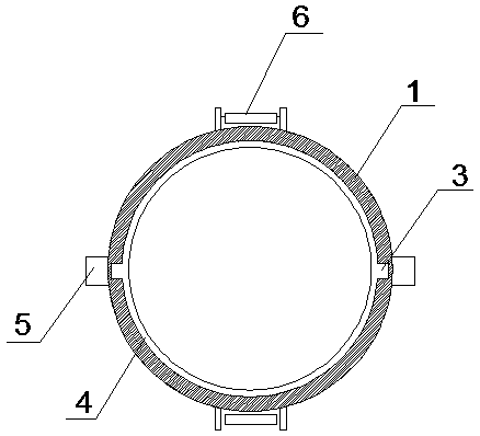
[0030] A plug-in insulating sleeve provided in this embodiment has a structure such as figure 1 As shown, including a pipe body 1, the upper end surface of the pipe body 1 is fixedly provided with an insertion rod 2, the insertion rod 2 of this embodiment is an inverted L shape, and the lower end surface of the pipe body 1 is provided with an insertion rod 2 2 matching socket 3, the lower end surface of the tube body 1 is provided with a cavity 4 for the insertion rod 2 to move, by inserting the insertion rod 2 into the socket 3 and then rotating, the lateral part of the insertion rod 2 is rotated to In the cavity 4, the upper and lower positions between the two insulating sleeves can be fixed;
[0031] The side of the pipe body 1 is provided with a bump 5, the bump 5 is located at the lower part of the side of the pipe body 1, two of the bumps 5 are arranged, and they are located on the same diameter of the end face of the pipe body 1, the pipe body 1 The side is hinged with...
Embodiment 2
[0040] A plug-in insulating sleeve provided in this embodiment has a structure such as figure 1 As shown, including a pipe body 1, the upper end surface of the pipe body 1 is fixedly provided with an insertion rod 2, the insertion rod 2 of this embodiment is an inverted L shape, and the lower end surface of the pipe body 1 is provided with an insertion rod 2 2 matching socket 3, the lower end surface of the tube body 1 is provided with a cavity 4 for the insertion rod 2 to move, by inserting the insertion rod 2 into the socket 3 and then rotating, the lateral part of the insertion rod 2 is rotated to In the cavity 4, the upper and lower positions between the two insulating sleeves can be fixed;
[0041] The side of the pipe body 1 is provided with a bump 5, the bump 5 is located at the bottom of the side of the pipe body 1, the side of the pipe body 1 is hinged with a cover plate 6, the cover plate 6 is located at the top of the side of the pipe body 1, and the cover plate 6 ...
Embodiment 3
[0050] A plug-in insulating sleeve provided in this embodiment has a structure such as figure 1 As shown, including a pipe body 1, the upper end surface of the pipe body 1 is fixedly provided with an insertion rod 2, the insertion rod 2 of this embodiment is an inverted L shape, and the lower end surface of the pipe body 1 is provided with an insertion rod 2 2 matching socket 3, the lower end surface of the tube body 1 is provided with a cavity 4 for the insertion rod 2 to move, by inserting the insertion rod 2 into the socket 3 and then rotating, the lateral part of the insertion rod 2 is rotated to In the cavity 4, the upper and lower positions between the two insulating sleeves can be fixed;
[0051] The side of the pipe body 1 is provided with a bump 5, the bump 5 is located at the bottom of the side of the pipe body 1, the side of the pipe body 1 is hinged with a cover plate 6, the cover plate 6 is located at the top of the side of the pipe body 1, and the cover plate 6 ...
PUM
 Abstract
Description
Claims
Application Information
 - R&D
- Intellectual Property
- Life Sciences
- Materials
- Tech Scout
- Unparalleled Data Quality
- Higher Quality Content
- 60% Fewer Hallucinations
Browse by: Latest US Patents, China's latest patents, Technical Efficacy Thesaurus, Application Domain, Technology Topic, Popular Technical Reports.
© 2025 PatSnap. All rights reserved.Legal|Privacy policy|Modern Slavery Act Transparency Statement|Sitemap|About US| Contact US: help@patsnap.com


