Antenna feeder arranged on plane horizontal tails and connected with radio altimeter

A technology of radio altimeter and antenna feeder, which is applied in the field of antenna feeder to increase the turning radius, avoid tracking false signals, and reduce mutual influence

Inactive Publication Date: 2018-02-23
NANJING UNIV OF AERONAUTICS & ASTRONAUTICS
View PDF8 Cites 2 Cited by
  • Summary
  • Abstract
  • Description
  • Claims
  • Application Information

AI Technical Summary

Problems solved by technology

However, there is no patent or literature related to the method of installing the radio altimeter antenna feeder at the horizontal tail of the aircraft.

Method used


Image

  • Antenna feeder arranged on plane horizontal tails and connected with radio altimeter
  • Antenna feeder arranged on plane horizontal tails and connected with radio altimeter
  • Antenna feeder arranged on plane horizontal tails and connected with radio altimeter

Examples


Embodiment Construction

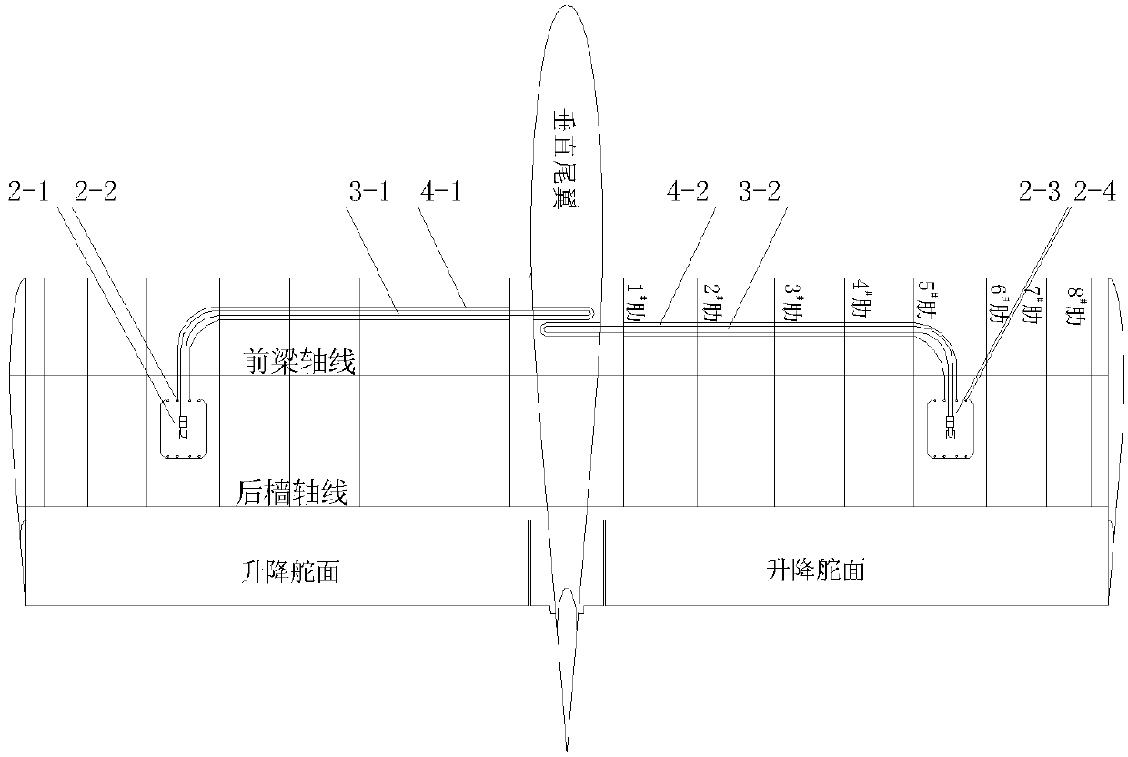
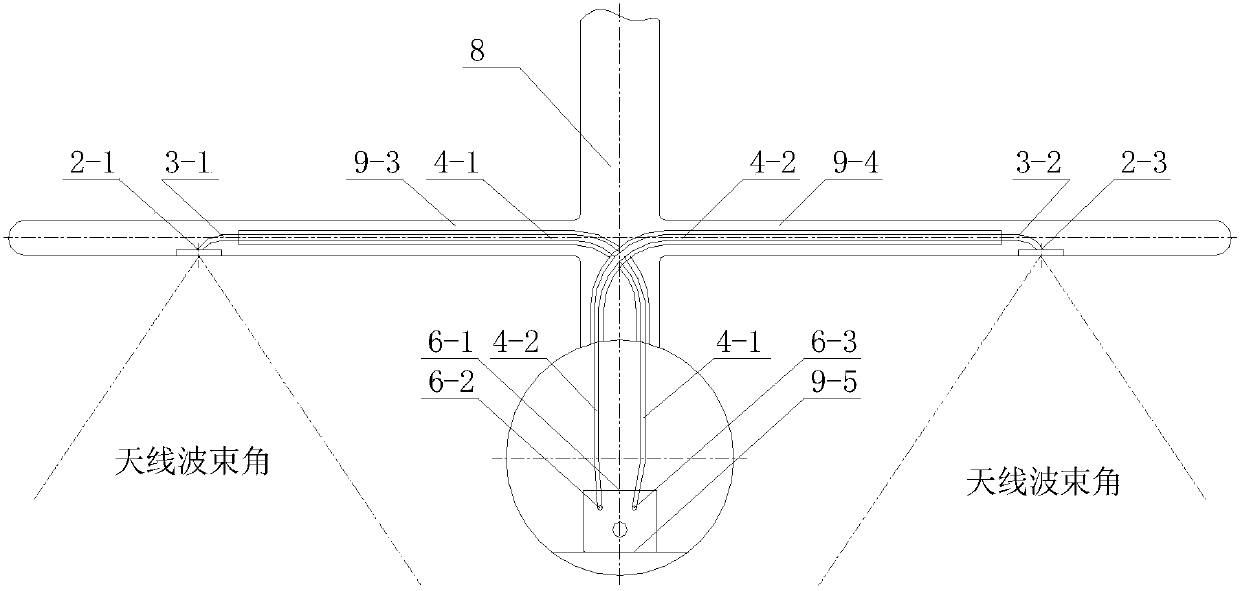
[0010] Because the lower surface of the aircraft wing is relatively flat, it is an ideal location for microstrip antenna installation. However, since the wing is in the middle of the fuselage, and the radio altimeter is installed in the rear cabin of the aircraft, the length of the sending and receiving feeder wires needs to be more than 5m; Tracer tubes, GPS antennas, communication antennas, etc. are easy to interact and interfere with each other, and it is difficult to coordinate the installation positions.

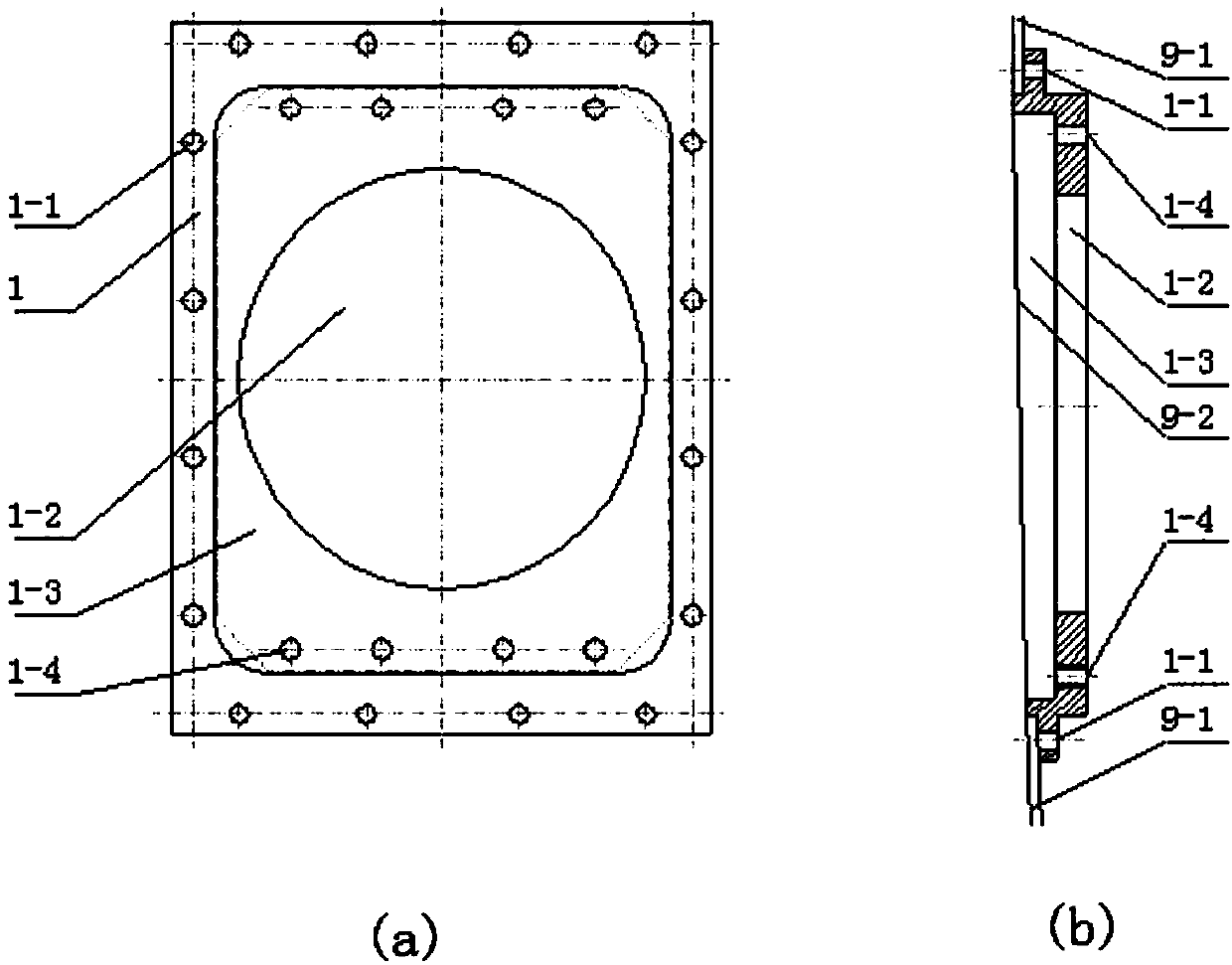
[0011] Since the lower surface of the aircraft's horizontal tail is also relatively flat, there is no other equipment except for the steering gear transmission mechanism, such as installing the microstrip antenna on the lower surface of the aircraft's horizontal tail. The length of each is 2.5m, which can meet the installation requirements of the radio altimeter antenna feeder. However, the installation space of the aircraft's horizontal tail is narrow, and an effectiv...


PUM


Abstract

The invention provides an antenna feeder which is arranged on plane horizontal tails and is connected with a radio altimeter. The antenna feeder comprises a receiving microstrip antenna, a transmitting microstrip antenna, a receiving feeder and a transmitting feeder. The receiving microstrip antenna and the transmitting microstrip antenna are located in horizontal tails on both sides of a verticalstabilizer respectively. The receiving feeder is connected with the receiving microstrip antenna and the radio altimeter. The transmitting feeder is connected with the transmitting microstrip antennaand the radio altimeter. The receiving feeder and the transmitting feeder are crossed to come into the fuselage from the horizontal tails.

Description

technical field [0001] The invention relates to an aircraft recording equipment installation technology, in particular to an antenna feeder installed on the horizontal tail of an aircraft and connected with a radio altimeter. Background technique [0002] Microstrip antennas are generally used in the frequency range of 1 to 50 GHz, and special antennas can also be used for tens of megahertz. Compared with commonly used microwave antennas, it has the characteristics of small size, light weight, low profile, and can conform to the carrier. There have been many studies on microstrip antennas in the prior art: the patent application number 201610266415.2 discloses an ultra-wideband microstrip antenna based on a rectangular ladder structure fractal, and "Microstrip Conformal Antenna Array in Telemetry System" published by Li Zhiyong Design and Application of Microstrip Antenna” discloses a design method of microstrip conformal antenna array. Xiao Xiandong’s “Design and Applicati...

Claims


Application Information

Patent Timeline
Patent Type & Authority Applications(China)
IPC IPC(8): H01Q1/12H01Q1/38H01Q1/50B64C1/36
CPCH01Q1/12B64C1/36H01Q1/38H01Q1/50
Inventor 王少云尹海莲郭静
Owner NANJING UNIV OF AERONAUTICS & ASTRONAUTICS
Why Eureka
Try Eureka