Novel traction bottom roller

A new type of technology for rollers, applied in drafting equipment, textiles, papermaking, spinning machines, etc., can solve the problems of complicated preparation process, increased production cost, poor practicability, etc., achieve unique structural design, improve production efficiency, The effect of flexible and convenient disassembly

Inactive Publication Date: 2013-03-20
SUZHOU XUNXIAN TEXTILE TECH CO LTD
View PDF5 Cites 4 Cited by
  • Summary
  • Abstract
  • Description
  • Claims
  • Application Information

AI Technical Summary

Problems solved by technology

However, the strengthening cost is too high, the preparation process is complicated, and the practicability is not good. At the same time, the groove structure and the optical axis are designed as an

Method used


Image

  • Novel traction bottom roller

Examples


Example Embodiment

[0016] The preferred embodiments of the present invention will be described in detail below in conjunction with the accompanying drawings, so that the advantages and features of the present invention can be more easily understood by those skilled in the art, so as to define the protection scope of the present invention more clearly.

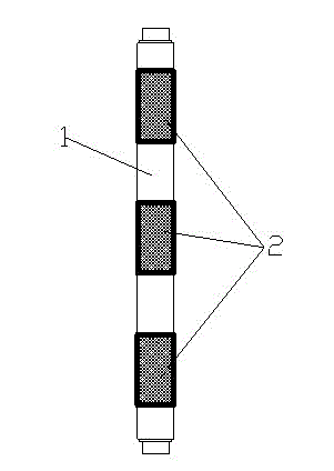
[0017] figure 1 It is a schematic diagram of the structure of the new traction bottom roller in the embodiment of the present invention; the bottom roller includes an optical axis base 1 and a groove sleeve 2, the material of the optical axis base 1 is 45 steel, and the material of the groove sleeve 2 is It is made of non-metallic material, the grooved sleeve 2 and the optical axis base 1 are bonded and connected by hot melt adhesive, and the grooved sleeve 2 can be disassembled and replaced after wear.

[0018] The material of the grooved sleeve 2 of the new traction bottom roller mentioned in the present invention generally selects engineering ...


PUM

PropertyMeasurementUnit
Surface roughnessaaaaaaaaaa

Abstract

The invention provides a novel traction bottom roller. The bottom roller comprises a smooth shaft base body and groove sleeves, wherein the smooth shaft base body is made from 45# steel; each groove sleeve is made from a nonmetal material; each groove sleeve and the smooth shaft base body are connected in an adhesion way through the adoption of a hot melting adhesive; and after the wearing, each groove sleeve can be detached for replacement. The invention discloses the novel traction bottom roller; the traction bottom roller is unique in structure design and stable in performance; groove structures on the smooth shaft base body are replaced by the groove sleeves; a smooth shaft is unnecessarily machined, so that the production efficiency of the traction bottom roller is improved; meanwhile, the groove sleeves are flexible and convenient to install and detach; moreover, various sleeve materials can be selected for the sleeves for adaptation to various production demands; and in such a way, the traction bottom roller is enabled to be more practical.

Description

technical field [0001] The invention relates to a pulling bottom roller, in particular to a novel pulling bottom roller whose groove structure can be independently prepared and replaced, and belongs to the technical field of textile accessories. Background technique [0002] The traction bottom roller on the textile machine is composed of an optical axis, a groove structure arranged at intervals and a connecting end. The groove structure on the pulling bottom roller and the top roller on the top roller form a jaw to hold and pull the yarn. Ordinary lower pulling rollers are made of 45 steel or 20 carburized steel as a whole. The lower pulling rollers are exposed in the air and are easily corroded. At the same time, the friction between the groove structure on the lower pulling rollers and the top rollers is relatively large. The tooth shape on the groove structure is easy to be blunt, which reduces the service life of the lower pulling roller, and aggravates the fluctuation...

Claims


Application Information

Patent Timeline
IPC IPC(8): D01H5/78D01H5/80
Inventor 王俊云
Owner SUZHOU XUNXIAN TEXTILE TECH CO LTD
Why Eureka
Try Eureka