
Power management method and device

A power management and power management chip technology, applied in the field of communications, can solve the problems of PM chip thermal power consumption, increase battery energy consumption, battery consumption, etc., to achieve the effect of extending battery life, improving work performance, and avoiding uneven load

Active Publication Date: 2021-03-16
BEIJING XIAOMI MOBILE SOFTWARE CO LTD
View PDF4 Cites 0 Cited by
  • Summary
  • Abstract
  • Description
  • Claims
  • Application Information

AI Technical Summary

Problems solved by technology

When only one PM chip supplies power to the CPU, the current passing through the PM chip is very large, the working efficiency of the PM chip is low, and the thermal power consumption generated on the PM chip is large, resulting in a large heat flux density and high temperature rise of a single PM chip. Reduced lifetime and performance of the PM chip
Moreover, the energy consumption of the battery will be more, so that the battery life of the terminal equipment will be reduced.
[0004] In the related technology, in order to ensure the high-power operation of the central processing unit, two PM chips are usually configured in the terminal device. However, in the related technology, even if the CPU power demand is huge, most of the power can only be It is supplied by one of the two PM chips, resulting in a large current passing through the PM chip, the thermal power consumption of the PM chip is very large, and the total thermal power consumption of the two PM chips will also be large, resulting in the PM chip The service life and working performance are seriously reduced, and the energy consumption of the battery is increased, which reduces the battery life of the terminal equipment

Method used


Image

  • Power management method and device
  • Power management method and device
  • Power management method and device

Examples


Embodiment Construction

[0032] Reference will now be made in detail to the exemplary embodiments, examples of which are illustrated in the accompanying drawings. When the following description refers to the accompanying drawings, the same numerals in different drawings refer to the same or similar elements unless otherwise indicated. The implementations described in the following exemplary examples do not represent all implementations consistent with the present disclosure. Rather, they are merely examples of apparatuses and methods consistent with aspects of the present disclosure as recited in the appended claims.

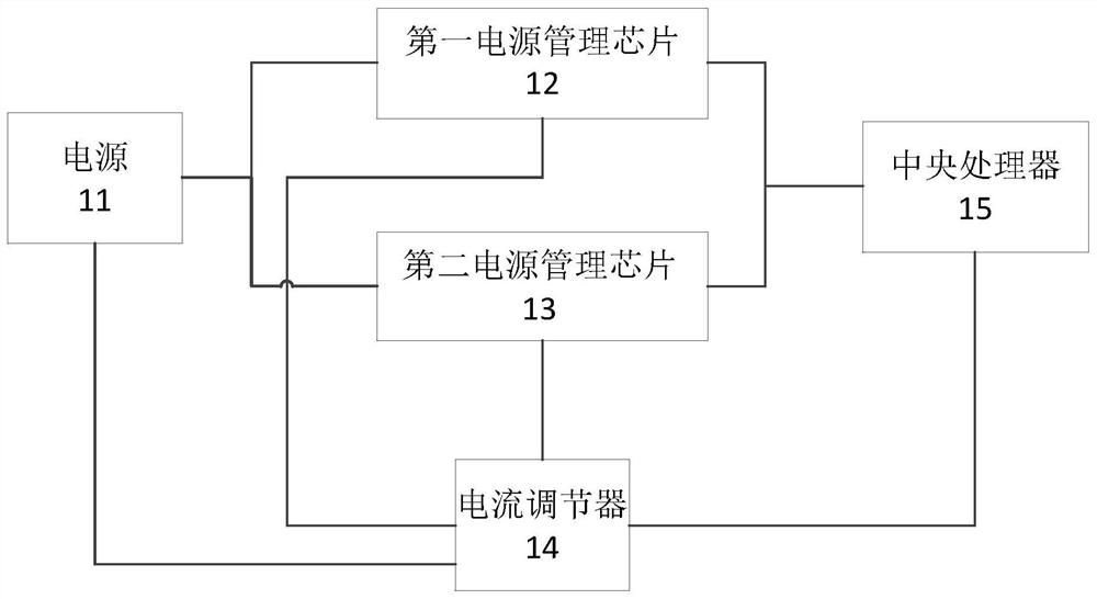
[0033] figure 1 It is a schematic diagram of an application scenario of a power management method according to an exemplary embodiment. The method can be applied to electronic equipment including at least two power management chips. figure 1 It schematically shows the connection relationship between the current regulator 14 and the power supply 11, the first power management chip 12,...


PUM


Abstract

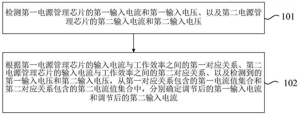
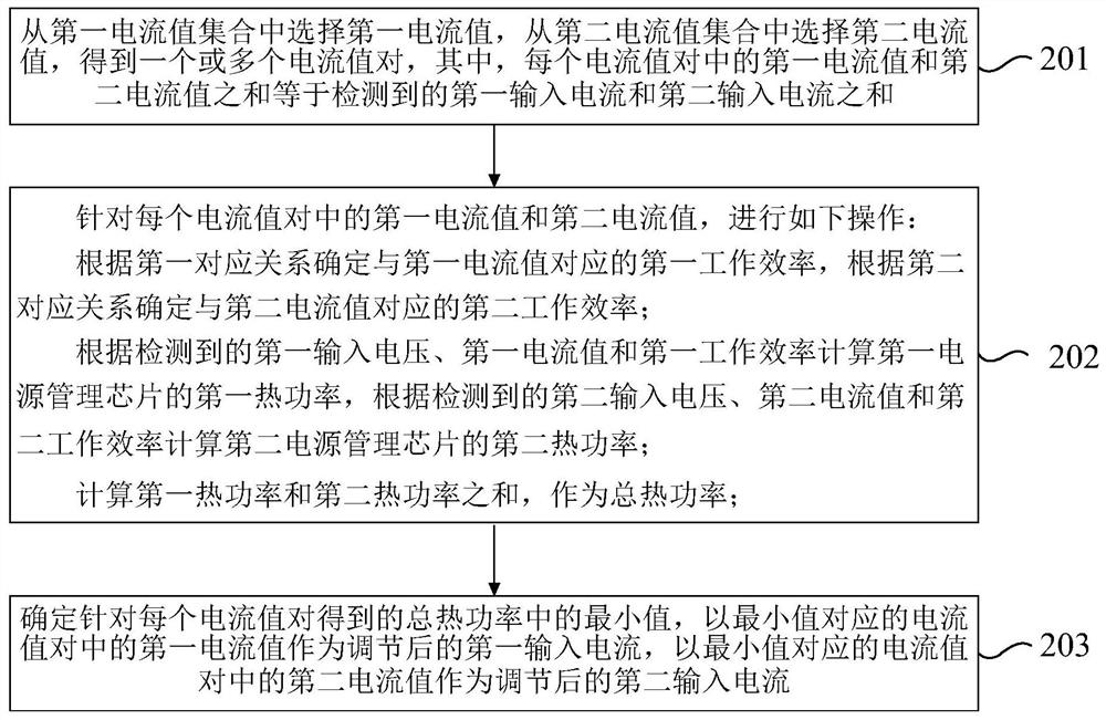
The present disclosure relates to a power management method and device. The present disclosure uses the detected first input current and first input voltage of the first power management chip and the second input current and second input of the second power management chip voltage, the first corresponding relationship between the input current of the first power management chip and the working efficiency, and the second corresponding relationship between the input current of the second power management chip and the working efficiency, respectively determine the adjusted first input current and The adjusted second input current, thus ensuring that the first power management chip and the second power management chip work at the same time when the system current is too large, reasonably distribute the input current of the two, and minimize the total thermal power consumption of the two , prolong the service life of the power management chip, improve the performance of the power management chip, reduce the energy consumption of the battery, and prolong the battery life of the terminal device.

Description

technical field [0001] The present disclosure relates to the field of communication technologies, and in particular, to a power management method and device. Background technique [0002] A power management (PM, Power Management) chip is a chip responsible for converting, distributing, and managing other electric energy in electronic equipment. It is mainly responsible for identifying the power supply amplitude of the central processing unit (CPU, Central Processing Unit), generating a corresponding short moment wave, and driving the power output of the subsequent stage circuit. Power management chips are widely used. With the development of information technology, power management chips are widely used in terminal equipment such as smartphones and other electronic devices. [0003] As the CPU becomes more and more powerful, the calculation speed is higher and higher, and the electrical power required is also increasing, which leads to an increasing electrical power output ...

Claims


Application Information

Patent Timeline
Patent Type & Authority Patents(China)
IPC IPC(8): H04W52/02H04M1/724H04M1/72454
CPCH04W52/0261H04M1/724Y02D30/70
Inventor 王畅
Owner BEIJING XIAOMI MOBILE SOFTWARE CO LTD
Learn More