
Gastrointestinal tube

A gastrointestinal and catheter technology, applied in the field of medical devices, can solve problems such as difficulties, and achieve the effect of reducing work intensity and operating requirements.

Inactive Publication Date: 2018-02-27
来奉田
View PDF10 Cites 2 Cited by
  • Summary
  • Abstract
  • Description
  • Claims
  • Application Information

AI Technical Summary

Problems solved by technology

[0003] However, it is very difficult to insert the existing gastrointestinal tube, and there are very professional medical staff to operate it

Method used


Image

  • Gastrointestinal tube
  • Gastrointestinal tube
  • Gastrointestinal tube

Examples


Embodiment Construction

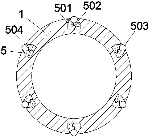
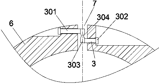
[0016] Example: such as figure 1 , 2 As shown in , 3, a gastrointestinal tube includes a catheter 1 and a joint 2 connecting the front end of the catheter 1 and a lateral passage hole 4 on the end of the catheter 1; the end of the catheter 1 is provided with a pressure lubricating part 5. The applicant found that when intubating, it is necessary to position the patient, clean and lubricate the nasal cavity. Tilt the patient's head back and insert the tube at an angle of 60° to the nostril, and continue to insert into the nasopharynx; but , it is more difficult to continue to insert, because it needs to go through the throat, so generally more experienced medical personnel are required to operate, but the operation is laborious and needs to be careful, so the applicant developed the scheme of this application, setting The pressure lubricating part is installed, and when passing through the throat, it can perform corresponding lubrication, thereby reducing the difficulty of ope...


PUM

PropertyMeasurementUnit
Lengthaaaaaaaaaa

Abstract

The invention discloses a gastrointestinal tube, which comprises a catheter, a joint connected to the front end of the catheter, and a lateral clearing hole formed in the tail end of the catheter. Thetail end of the catheter is provided with a pressed lubricating part. The gastrointestinal tube is relatively easy and smooth to insert into a human body, and requirements for operation of medical personnel are relatively low, so that working intensity of medical personnel is reduced.

Description

technical field [0001] The invention relates to the technical field of medical instruments, in particular to a gastrointestinal tube. Background technique [0002] Gastrointestinal tube, also known as nasogastric tube and nasal feeding tube, is inserted through the nostril, passes through the pharynx, and reaches the stomach through the esophagus. It is mostly used to pump gastric juice, and can also be used to inject liquid into the stomach to provide patients with necessary food. and nutrition. For example, Chinese invention patent CN 201010609390.4 discloses a new type of gastric tube, which includes a gastric tube body. A guide wire is arranged in the lumen of the gastric tube body along the direction of the gastric tube, and the rear end of the guide wire protrudes from the gastric tube body. The invention increases the plasticity of the gastric tube and makes the gastric tube have certain toughness and bendability owing to being provided with a guide wire in the gastr...

Claims


Application Information

Patent Timeline
IPC IPC(8): A61J15/00A61M31/00
CPCA61J15/0003A61J15/0026A61M31/00A61M2210/065A61M2210/005
Inventor 来奉田
Owner 来奉田
Learn More