
Copper tile bearing pedestal convenient to install

A technology that facilitates installation and bearing housing. It is used in bearing components, shafts and bearings, and rigid supports for bearing components. It can solve the problems of poor equipment stability, inconvenient use, and cumbersome installation process, and reduce the possibility of damage to machinery. , Simple installation and disassembly, convenient installation effect

Inactive Publication Date: 2018-02-27
响水县冠龙轴承座制造有限公司
View PDF0 Cites 2 Cited by
  • Summary
  • Abstract
  • Description
  • Claims
  • Application Information

AI Technical Summary

Problems solved by technology

[0002] With the continuous development of society and the continuous updating of science and technology, my country's manufacturing industry has developed rapidly, and machinery manufacturing is particularly prominent in the manufacturing industry. Bearings, as important equipment in the machinery manufacturing process, have received more and more attention from people. Bearings are not It may be used alone and must be equipped with an external support structure. The bearing seat is often called an external support. The bearing seat is a structure that receives comprehensive loads and has a special structure. It has the characteristics of compact structure and sensitive rotation. At present, the bearing seat is widely used. However, there are some deficiencies in the use of the bearing housings currently on the market. The structure of the bearing housings is complicated, the installation process is cumbersome, and the equipment stability is poor due to the unreasonable installation structure during the use process, which brings many problems to the use. inconvenient

Method used


Image

  • Copper tile bearing pedestal convenient to install
  • Copper tile bearing pedestal convenient to install
  • Copper tile bearing pedestal convenient to install

Examples


Embodiment Construction

[0016] The following will clearly and completely describe the technical solutions in the embodiments of the present invention with reference to the accompanying drawings in the embodiments of the present invention. Obviously, the described embodiments are only some, not all, embodiments of the present invention.

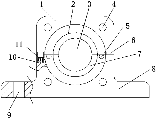
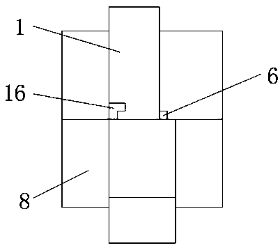
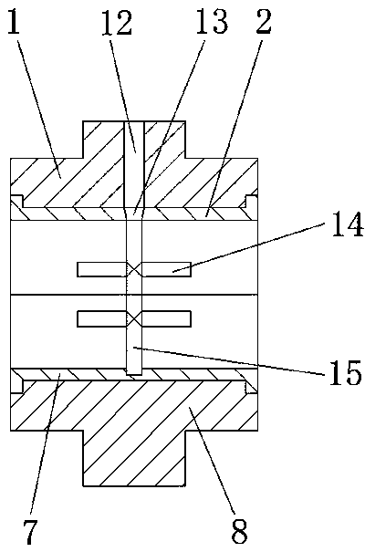
[0017] refer to Figure 1-3 , a copper tile bearing seat for easy installation, including a lower cover body 8, mounting holes 9 are opened on both sides of the bottom outer wall of the lower cover body 8, and L-shaped bumps (16 ), both sides of the top outer wall of the lower cover 8 have limiting grooves 10, and the bottom inner walls of the two limiting grooves 10 are fixed with springs 11 by screws, and the top outer walls of the two springs 11 are fixed by screws to limit the block 6 , and the outer walls on both sides of the two limiting blocks 6 are slidably connected to the inner walls on both sides of the limiting groove 10, the outer walls of the top of the...


PUM


Abstract

The invention discloses an easy-to-install copper tile bearing seat, which comprises a lower cover body. Mounting holes are opened on both sides of the bottom outer wall of the lower cover body, and L-shaped bumps are welded on both sides of the top outer wall of the lower cover body. Limiting grooves are opened on both sides of the top outer wall of the lower cover, and the bottom inner walls of the two limiting grooves are fixed with springs by screws, and the top outer walls of the two springs are fixed with limiting blocks by screws, and the two The outer walls on both sides of the limiting block are slidably connected to the inner walls on both sides of the limiting groove, connecting grooves are opened on both sides of the outer wall on the top of the lower cover, and connecting columns are slidably connected to the inner walls of the two connecting grooves. The invention makes the installation and disassembly of the upper cover and the lower cover simple through the sliding fit of the connecting column and the connecting groove, and the axial installation of the upper cover can be made firm through the cooperation of the limit block and the L-shaped protrusion. The cooperation of the block and the clamping hole can ensure the stability of the radial installation of the upper cover and the lower cover.

Description

technical field [0001] The invention relates to the technical field of copper tile bearing seats, in particular to a conveniently installed copper tile bearing seat. Background technique [0002] With the continuous development of society and the continuous updating of science and technology, my country's manufacturing industry has developed rapidly, and machinery manufacturing is particularly prominent in the manufacturing industry. Bearings, as important equipment in the machinery manufacturing process, have received more and more attention from people. Bearings are not It may be used alone and must be equipped with an external support structure. The bearing seat is often called an external support. The bearing seat is a structure that receives comprehensive loads and has a special structure. It has the characteristics of compact structure and sensitive rotation. At present, the bearing seat is widely used. However, there are some deficiencies in the use of the bearing housi...

Claims


Application Information

Patent Timeline
IPC IPC(8): F16C35/02
CPCF16C35/02
Inventor 杨燕燕
Owner 响水县冠龙轴承座制造有限公司
Features
  • Generate Ideas
  • Intellectual Property
  • Life Sciences
  • Materials
  • Tech Scout
  • Unparalleled Data Quality
  • Higher Quality Content
  • 60% Fewer Hallucinations
Learn More