Pipeline robot detection device and pipeline fault detection method

A pipeline robot and detection device technology, which is applied in the direction of pipes/pipe joints/fittings, special pipes, pipe components, etc., can solve the problems of inability to accurately detect pipeline operating conditions and limited detection range of detection devices

Pending Publication Date: 2018-02-27
珠海深圳清华大学研究院创新中心
View PDF9 Cites 10 Cited by
  • Summary
  • Abstract
  • Description
  • Claims
  • Application Information

AI Technical Summary

Problems solved by technology

[0004] Therefore, the technical problem to be solved by the embodiments of the present invention is that the detection devices in the prior art are generally installed on the body of the pipeline robo

Method used


Image

  • Pipeline robot detection device and pipeline fault detection method
  • Pipeline robot detection device and pipeline fault detection method
  • Pipeline robot detection device and pipeline fault detection method

Examples


Embodiment 1

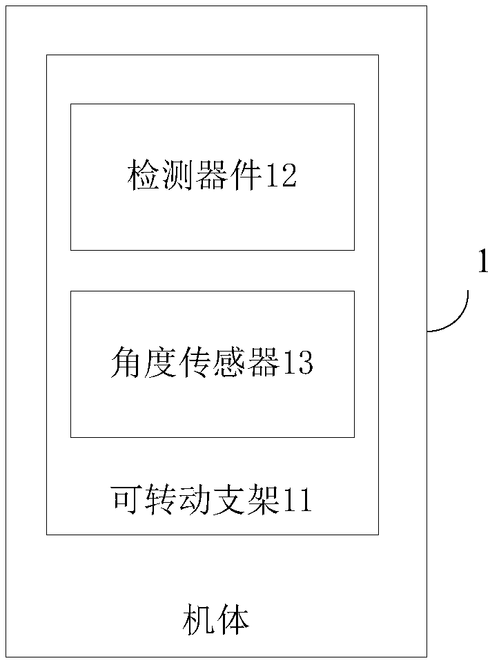
[0041] An embodiment of the present invention provides a pipeline robot detection device, such as figure 1 As shown, it includes a body 1, including: at least one set of rotatable brackets 11, which are installed on the body 1 and can rotate to a first preset angle; detection devices 12, which are installed on the rotatable brackets 11, are used to detect whether the pipeline Fault; the angle sensor 13 is arranged inside the rotatable support 11 and is used to detect the current rotation angle of the rotatable support 11 .

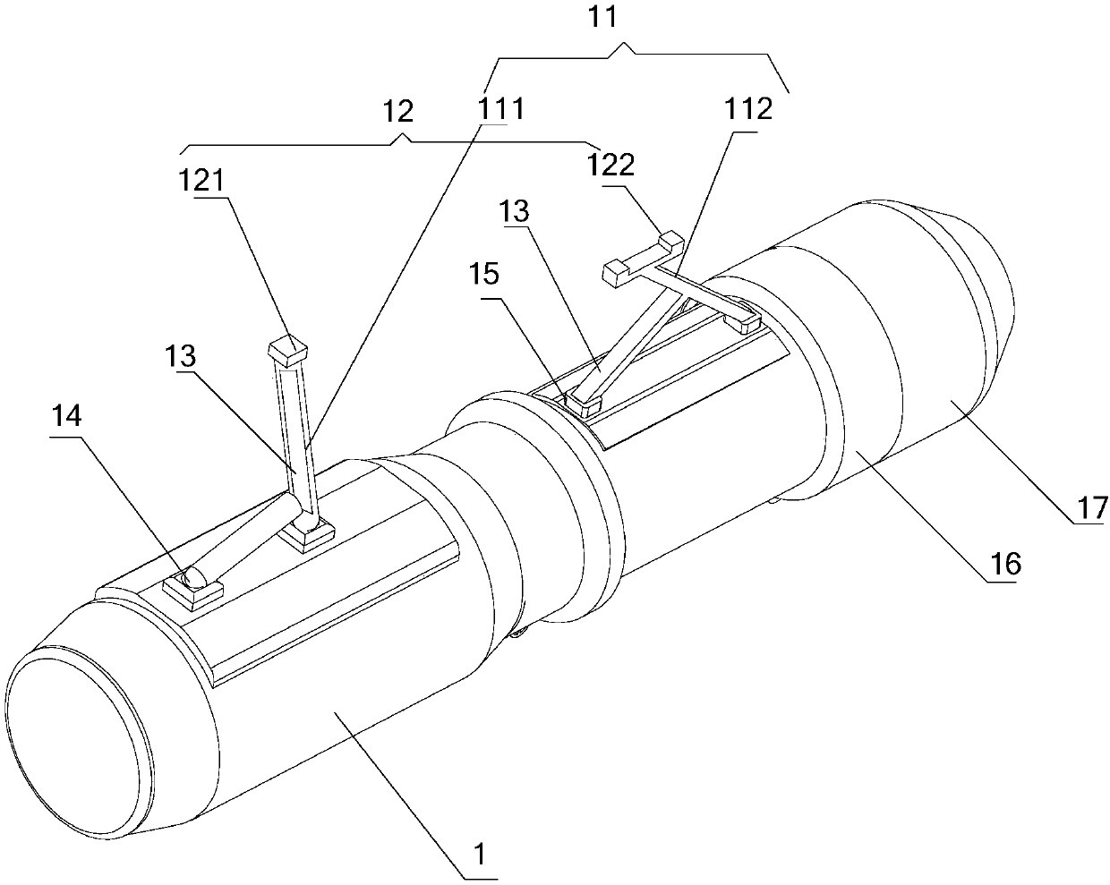
[0042] Specifically, such as figure 2 As shown, the rotatable bracket 11 includes a first variable-diameter bracket 111 and a second variable-diameter bracket 112, wherein the first variable-diameter bracket 111 is connected to the body 1 through a fixed hinge 14, and the first variable-diameter bracket 111 is located at the front of the body 1. The second reducing bracket 112 is connected with the body 1 through the hinge plate 15, the second reducing b...

Embodiment 2

[0055] The pipeline robot detection device provided by the embodiment of the present invention, the embodiment of the present invention provides a pipeline robot detection device, such as figure 1 and figure 2 As shown, it includes a body 1, including: at least one set of rotatable brackets 11, which are installed on the body 1 and can rotate to a first preset angle; detection devices 12, which are installed on the rotatable brackets 11, are used to detect whether the pipeline Fault; the angle sensor 13 is arranged inside the rotatable support 11 and is used to detect the current rotation angle of the rotatable support 11 . It also includes a control panel arranged outside the pipeline, on which a control circuit is arranged and connected to the detection device 12 and the angle sensor 13 respectively.

[0056] Specifically, the control circuit is connected to the angle sensor 13 through a cable signal transmission line provided inside the body 1 . The control circuit inclu...

Embodiment 3

[0059] An embodiment of the present invention provides a pipeline fault detection method, which is used in the pipeline robot detection device in Embodiment 1 and Embodiment 2, such as Figure 4 shown, including the following steps:


PUM


Abstract

The invention discloses a pipeline robot detection device and a pipeline fault detection method. The pipeline robot detection device comprises a machine body, at least one rotatable support, detectioncomponents and angle sensors, wherein the rotatable supports are installed on the machine body and can rotate to first preset angles. The detection components are arranged on the rotatable supports and are used for detecting whether a pipeline fails or not, and the angle sensors are arranged in the rotatable supports and are used for detecting the current rotation angles of the rotatable supports. The rotatable supports can rotate, and the detection range can be expanded by utilizing the detection components arranged on the rotatable supports, so that the detection components can accurately detect detailed faults in the pipeline, the fault detection precision is improved, the pipeline can be repaired in time by manpower, and safe operation of the pipeline is ensured.

Description

technical field [0001] The invention relates to the technical field of pipeline robots, in particular to a pipeline robot detection device and a pipeline fault detection method. Background technique [0002] With the rapid development of society, the infrastructure construction is also developing rapidly, and more and more various pipelines are laid in various buildings. During the transportation of time, dirt will accumulate in the pipeline, and the pipeline wall will be damaged and thinned or even partially ruptured. These all restrict the development of pipeline transportation, and this has gradually become a difficult point for maintenance. Therefore, we have to cooperate with the pipeline robot for regular maintenance. The pipeline robot is a kind of machine that can automatically walk along the inside or outside of a small pipeline and carry one or more sensors and operating machinery. Series of pipeline operations. [0003] At present, in the traditional pipeline ro...

Claims


Application Information

Patent Timeline
IPC IPC(8): F16L55/32F16L101/30
CPCF16L55/32F16L2101/30Y02E30/30
Inventor 孟强张振涛侯伟钦
Owner 珠海深圳清华大学研究院创新中心
Why Eureka
Try Eureka