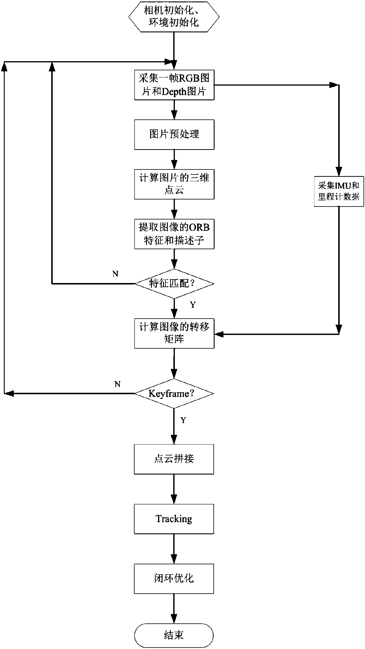
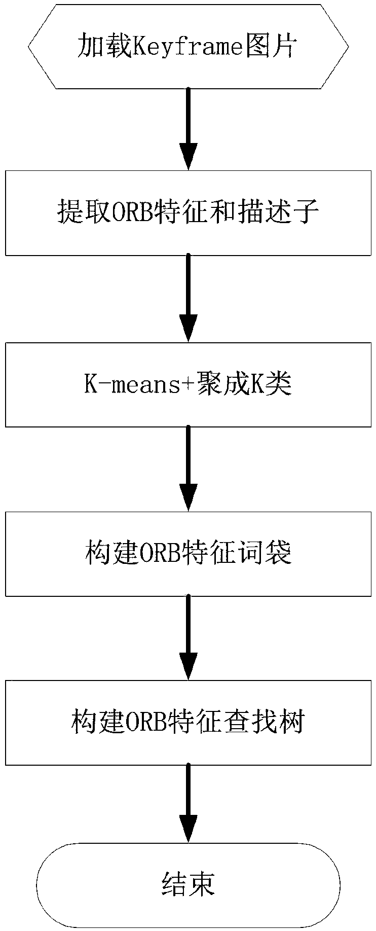
[0032] In the present invention, a method for constructing a map is proposed, which is mainly used in the field of visual positioning to generate a KeyFrame (key frame) of the surrounding environment, thereby realizing effective visual positioning. Although real-time mapping, positioning and navigation are popular at present, the 3D point cloud image established by real-time mapping is not accurate enough, and many problems are prone to occur as the map increases. Therefore, in the embodiment of the present invention, the The method for constructing a map in an offline state adopts the offline map, and in this embodiment, a positioning method of visual positioning fusion of IMU and odometer data is proposed to solve the positioning problem of the robot when the visual positioning fails, specifically Generate a Keypoint and Descriptor search tree through the image keyframes generated during map construction to improve the speed of visual positioning, and use PCA (Principal Component Analysis) principal component analysis on the 3D point cloud image of the environment formed during the map construction stage , analyze the direction of the point cloud space, calculate the projection parameters of the 3D point cloud, and generate a reference 2D map projected to the ground for robot positioning and path planning. The embodiment of the present invention is based on Intel's RealSense depth camera for mapping, positioning and navigation, and at the same time fuses IMU and odometer data for auxiliary positioning, thereby improving the robustness of the positioning algorithm of the entire system, so that the robot does not move at any time. will fail to locate.
[0033] The technical solutions of the present invention will be further described below in conjunction with the embodiments and the accompanying drawings.
[0034] The present invention provides a method for constructing a map, and the map is applied in the visual positioning technology of a mobile robot, at least including the following steps:
[0035] A. Collect the RGB image and depth image in the robot application through the 3D camera, and calculate the parameters of the 3D point cloud;
[0036] B. Extract the ORB features and descriptors of the collected images, splice the images of the 3D point cloud of the surrounding environment, and generate key frames of RGB and depth images;
[0037] C. Generate a word bag based on the extracted ORB features and descriptors, perform clustering, and generate an ORB feature tree;
[0038] D. analyze the spatial direction in the three-dimensional point cloud, obtain the projection parameters of the three-dimensional point cloud space, and project the point cloud perpendicular to the ground to the ground as required to form a 2D map;
[0039] E. Obtain the positioning map and the key frame of the map required for the visual positioning of the mobile robot.
[0040] In an embodiment of the present invention, in the step A, image data is collected offline or online to perform three-dimensional point cloud calculation; in the step B, the translation and rotation between each adjacent frame is obtained through feature matching amount, and collect the IMU data and odometer data of each frame of image, calculate and obtain the camera motion amount, and construct the motion feature transfer matrix of the camera. In the step B, the FLANN algorithm is used to perform feature matching calculation on the two frames of images, and the Kalman filter algorithm is used to fuse the feature matching to calculate the motion amount of the camera. In the step B, only the image frames of the key frames are spliced, and the BA algorithm is used to perform closed-loop optimization on the point cloud map. In the step C, a K-Means clustering algorithm is used to construct a bag of words and generate a feature tree. In the step D, the direction of the three-dimensional point cloud space is analyzed and obtained by using the PCA method.
[0041] In the present invention, the map can be constructed offline or online. In this embodiment, the method of constructing a map offline is used for specific description, because in the embodiment of the present invention, constructing a map offline helps to construct an accurate and complete environment When constructing a map, the ORB feature of the image is extracted, and then the 3D point cloud of the collected image is stitched into a 3D point cloud model of the entire environment. refer to figure 1 , the construction steps of the map are as follows: the 3D point cloud map in the present invention is constructed offline, using a 3D camera to collect RGB images and depth images, calculating the 3D point cloud, extracting the ORB features and descriptors of the picture, and splicing the 3D images of the surrounding environment Point cloud image, generate RGB and depth keyframes.
[0042] Specifically, in the offline 3D point cloud map construction algorithm, since visual positioning is essentially realized by using visual odometry, a 3D point cloud map of the pre-constructed environment or a 3D point cloud map is constructed for positioning, but in this implementation In the example, the 3D point cloud map of the environment is first constructed separately. When the 3D map is constructed, the present invention adds odometer data to the offline map construction method for map construction. Further reference figure 1 shown. In order to construct an accurate three-dimensional point cloud map, the translation and rotation between two adjacent frames calculated by feature matching are collected simultaneously with the IMU data and odometer data of each frame image, and the Kalman filter algorithm is used to fuse feature matching The calculated movement amount and the movement amount collected by the sensor are used to obtain a relatively accurate movement amount of the camera, and a camera movement feature transfer matrix is constructed. During feature matching, the FLANN algorithm (this algorithm is the content of the prior art, and will not be repeated here) is used for feature matching calculation. For the matching of two frames of images, there may be a situation that cannot be matched at all, and there may also be a large number of feature matching points, there are many wrong matching points, and we don’t need these feature matching points; or after matching the feature points, remove most of the unreasonable by gray histogram similarity, maximum matching and minimum matching feature matching points. When performing point cloud stitching, only the image frames selected as KeyFrame are stitched, and the stitching transfer matrix is the transfer matrix obtained by fusing multiple sensors. In order to reduce the error during stitching, the sparse BA algorithm can be used to perform closed-loop optimization on the stitched point cloud map.
[0043] Further, in order to reduce the time for robot positioning, in this embodiment, a bag of words is generated from the features and descriptors extracted from the 3D point cloud, and then a bag of words is constructed using the K-Means clustering algorithm, and an ORB feature tree is generated. Bags and feature trees are used in both the closed-loop optimization and localization phases.
[0044] In the actual use process, first extract and generate a dictionary of feature points and descriptors, and the internal words are the result of some feature clustering. The formed bag of words generates an ORB feature tree, such as figure 2 shown.
[0045] In addition, building a 3D point cloud map of the surrounding environment is the basis for positioning and navigation, but in practical applications, the map used by robots for positioning and navigation is a 2D map of the environment, and the generation of 2D maps is based on the 3D maps It is caused by the projection on a certain plane. It is obvious that the projected plane is the ground plane on which the robot walks. The 2D map generation process is as follows: First, the PCA method is used to analyze the direction of the three-dimensional point cloud space, and the three-dimensional point cloud space is calculated. The projection parameters; in order to reduce the impact of the three-dimensional point cloud space ceiling point cloud on the ground projection, in this embodiment, only certain range point clouds perpendicular to the ground are projected onto the ground to form a 2D map, such as image 3 shown.
[0046] The present invention also proposes a positioning method for a mobile robot using the above map construction method, comprising the following steps:
[0047] Real-time acquisition of RGB and depth images of the environment;
[0048] Preprocessing the collected image data, and matching and comparing with the key frames generated by constructing the map, to obtain the picture with the highest matching degree;
[0049] Calculate the obtained pictures, and obtain the absolute position and relative position information between the captured picture and the matching frame of the picture with the highest match;
[0050] The 2D position of the mobile robot is obtained by calculating the projection change from the 3D point cloud to the 2D map in the map.
[0051] In the solution of the present invention, it also includes acquiring IMU and mileage data parameters, and calculating and obtaining the incremental position value of the robot, and calibrating the positioning of the mobile robot. The calculation of the incremental position value of the robot includes: using Kalman filter algorithm to obtain the Euler angle of robot attitude; and calculating the incremental position and attitude angle of the robot by using mileage calculation model data.
[0052] The following specific examples are used for illustration. The visual positioning algorithm described in the present invention is mainly that the mobile robot collects the RGB and DEPTH maps of the environment in real time. After the pictures are preprocessed, they are matched with the Keyframe generated during map construction, and then the The location of the robot camera pose. The preprocessing of the image mainly includes the smoothing of the DEPTH image, the feature extraction of the image, and so on. The picture matching algorithm is to compare the collected pictures with each frame in Keframe, calculate 8 frames of similar candidate pictures, and finally select the picture with the best matching degree among the 8 pictures, so as to calculate the collected pictures. The absolute position and relative position between the picture and the matching frame, and calculate the positioned 2D position according to the projection change from 3D to 2D, such as Figure 4 shown.
[0053] Due to the influence of ambient light, depth information, texture feature information, etc. during visual positioning, the position that may be located during visual positioning may be deviated or cannot be located. At this time, the robot will lose its direction in the environment, so it will not Move to the next target position. In order to solve this problem, in the solution of the present invention, the heading angle of the robot calculated by the inertial measurement unit and the data of the encoder recorded by the odometer are fused into the positioning process of the robot. Among them, in the embodiment of the present invention, the heading angle solution refers to: use the Kalman filter algorithm to solve the original data in each direction from the 9-axis IMU unit to calculate the attitude representation value of the quaternion of the robot, thereby calculating Euler angles of the robot pose. Odometer model calculation: In the present invention, the positioning algorithm is not carried out every moment, and positioning is only started when positioning is required. Therefore, since the last positioning is completed, the incremental values of the encoders of the 4 motors when the next positioning is required are collected from the chassis of the mobile robot, and the movement of the robot in the X and Y directions is calculated through the kinematics calculation of the omnidirectional wheel Increment (the calculation process of determining the position of the robot is the content of the prior art, and will not be described in detail here). According to the value of the heading angle and the odometer model data, calculate the position increment and attitude angle of the robot after the last successful positioning. If the visual positioning is successful this time, the position increment value calculated by the IMU and mileage will be fused with the visual positioning result to calibrate the visual positioning result to obtain a more accurate positioning result; If the positioning fails, then according to the results of the last IMU and odometer positioning, plus the calculation value of this IMU and odometer, the final position of the robot is calculated as the position of this positioning, so as to improve the positioning efficiency of the robot. The positioning process is as Figure 5 shown.
[0054] In summary, the solution of the present invention has the following beneficial technical effects:
[0055] 1. When constructing a 3D point cloud map, an offline map construction method is proposed, and the odometer data is fused to construct the map to improve the accuracy of the established 3D map.
[0056] 2. When constructing a 3D point cloud map, the KeyPoint and Descriptor extracted from the KeyFrame of the generated image are clustered with K-Means to generate an ORB feature tree to improve the positioning speed of the robot.
[0057] 3. When projecting to generate a two-dimensional map, the method of projecting all point clouds within a certain distance from the ground and ceiling to a certain plane at the same time is adopted, so as to avoid the negative effects of projecting ceiling objects on the ground to path planning. At the same time, objects on the ground are projected to the plane of the ceiling projection, which is beneficial for the robot to avoid ground obstacles during path planning and improve the accuracy of obstacle avoidance.
[0058] 4. During positioning, an algorithm is proposed to fuse the results of visual positioning with heading angle and odometer data, so as to improve the accuracy and success rate of positioning.
[0059] The sequence of the above embodiments is only for convenience of description, and does not represent the advantages or disadvantages of the embodiments.
[0060] Finally, it should be noted that: the above embodiments are only used to illustrate the technical solutions of the present invention, rather than to limit them; although the present invention has been described in detail with reference to the foregoing embodiments, those of ordinary skill in the art should understand that: it can still be Modifications are made to the technical solutions described in the foregoing embodiments, or equivalent replacements are made to some of the technical features; and these modifications or replacements do not make the essence of the corresponding technical solutions deviate from the spirit and scope of the technical solutions of the various embodiments of the present invention.