

A hydraulic pump flow test device
A flow test device and hydraulic pump technology, applied in the direction of pump test, volume/mass flow generated by electromagnetic effect, liquid variable capacity machinery, etc., can solve the problem of only testing the instantaneous flow value, easy leakage of switching pipes, and flow sensor Easily damaged and other problems, to achieve the effect of overcoming single use function, fast switching, and eliminating purchase costs
Active Publication Date: 2014-10-22
NAVAL AERONAUTICAL & ASTRONAUTICAL UNIV PLA
View PDF0 Cites 2 Cited by
- Summary
- Abstract
- Description
- Claims
- Application Information
AI Technical Summary
Problems solved by technology
The purpose of the present invention is to overcome the deficiencies of the above-mentioned prior art, and provide a hydraulic pump flow test device, which mainly solves the problems of the existing hydraulic pump flow test device, such as inconvenient use, easy leakage when switching pipelines, and can only test instantaneous flow value, the flow sensor is easily damaged by impact for a long time, the price is expensive, and the cost performance is not high.
Method used
View moreImage
Smart ImageViewing Examples

Examples
Embodiment 1
Login to View More PUM
 Abstract
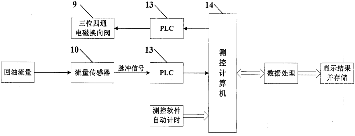
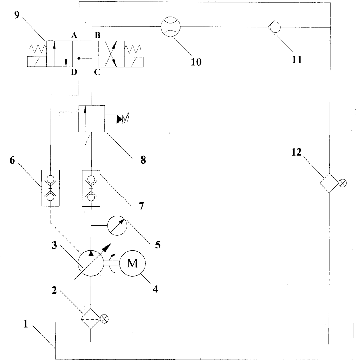
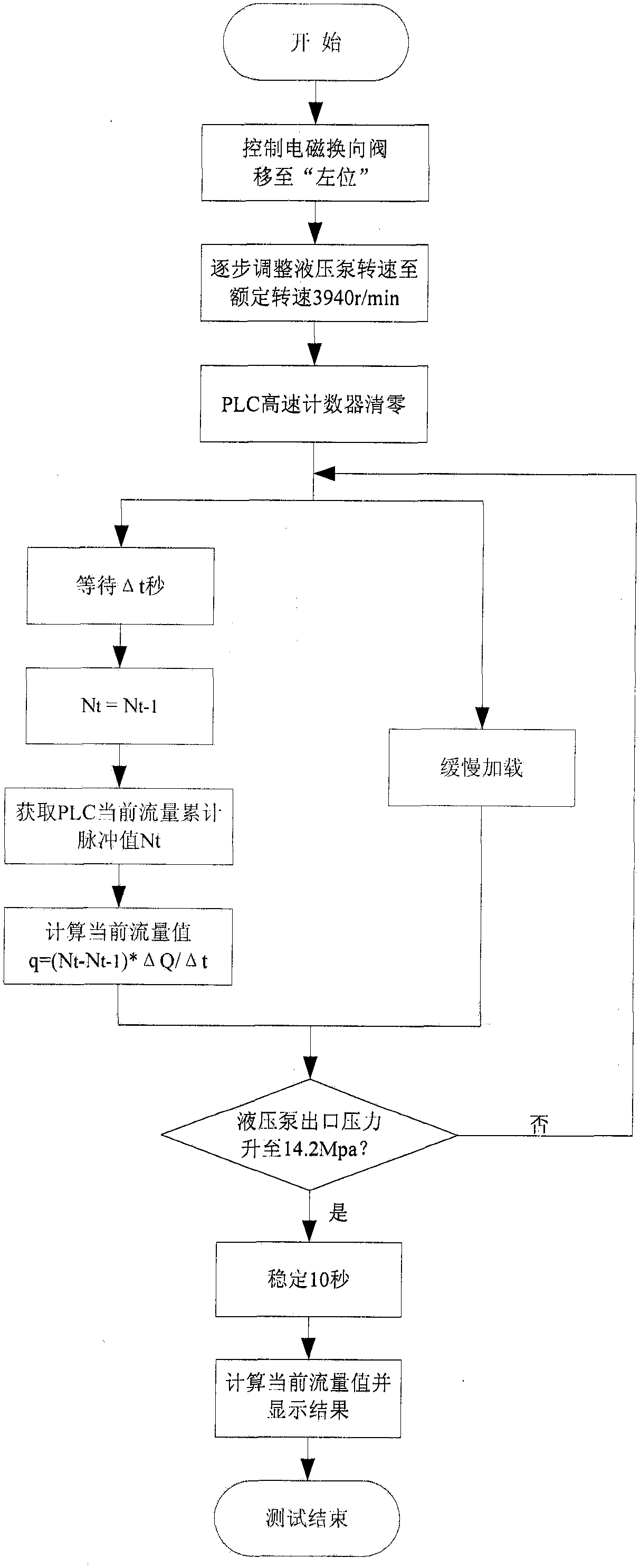
The utility model discloses a hydraulic pump flow test device, which comprises a hydraulic pump to be tested, a motor, a test bench, a hydraulic system and a circuit system, wherein the hydraulic system consists of a hydraulic source, a hydraulic pump oil suction circuit, and a hydraulic pump oil pressure circuit. , Hydraulic pump drain oil circuit, oil return circuit, the circuit system includes flow sensor, PLC, measurement and control computer. It is characterized in that a three-position four-way electromagnetic reversing valve is installed on the oil return circuit of the hydraulic system to realize the switching test of the outlet flow of the hydraulic pump and the oil return volume of the casing; the pulse output flow sensor is used instead of the voltage output flow sensor to realize instantaneous Test the flow value and oil volume in a certain period of time; use the PLC with high-speed counter function instead of the A / D acquisition card to collect the flow data of the flow sensor; the device is easy to use, complete in test items, and cost-effective, and has a good application and Promote prospects.
Description
technical field The invention relates to the technical field of hydraulic pump flow testing, in particular to a hydraulic pump flow testing device. Background technique The hydraulic system has the advantages of large power-to-mass ratio, simple control and adjustment, stable movement, easy to realize overload protection, self-lubricating and small wear between components, so it is widely used in military fields such as aviation, ships, and weapons. . The hydraulic system is mainly composed of power components, actuators, control components, auxiliary components and hydraulic oil. As the power component in the hydraulic system, the hydraulic pump is one of the most important components of the hydraulic system. The performance of the hydraulic pump directly affects the accuracy, stability and reliability of the output pressure and flow of the hydraulic system. The hydraulic pump test mainly refers to the test of the working performance of the hydraulic pump during deliver...
Claims
Login to View More Application Information
Patent Timeline
 Patent Type & AuthorityPatents(China)
IPC IPC(8): G01F1/56F04B51/00
Inventor刘书岩胡国才王秀霞刘湘一柳文林侯志强
OwnerNAVAL AERONAUTICAL & ASTRONAUTICAL UNIV PLA