Quick-clamped PCB gluing device

A technology of PCB board and gluing device, which is applied to the device and coating of surface coating liquid, which can solve the problems of inability to meet the coating requirements of PCB board, short circuit of circuit, high equipment cost, etc.

Inactive Publication Date: 2018-03-02
SUZHOU YILIHUA ELECTRONICS CO LTD
View PDF5 Cites 6 Cited by
  • Summary
  • Abstract
  • Description
  • Claims
  • Application Information

AI Technical Summary

Problems solved by technology

[0002] PCB multi-layer board refers to a multi-layer circuit board used in electrical products. Generally, it is a printed circuit board in which single-sided or double-sided boards are alternately connected together through a positioning system and insulating bonding materials, and the conductive patterns are interconnected according to design requirements. Such as four-layer and six-layer printed circuit boards, in the process of making PCB multilayer boards, it is necessary to coat the adhesive glue on the surface of the raw material board. In the existing method, a roller with bristles is often used to directly coat the glue. Since

Method used


Image

  • Quick-clamped PCB gluing device
  • Quick-clamped PCB gluing device
  • Quick-clamped PCB gluing device

Examples


Embodiment Construction

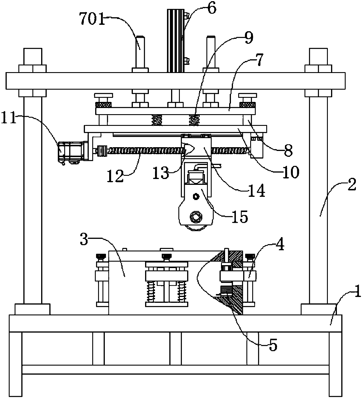
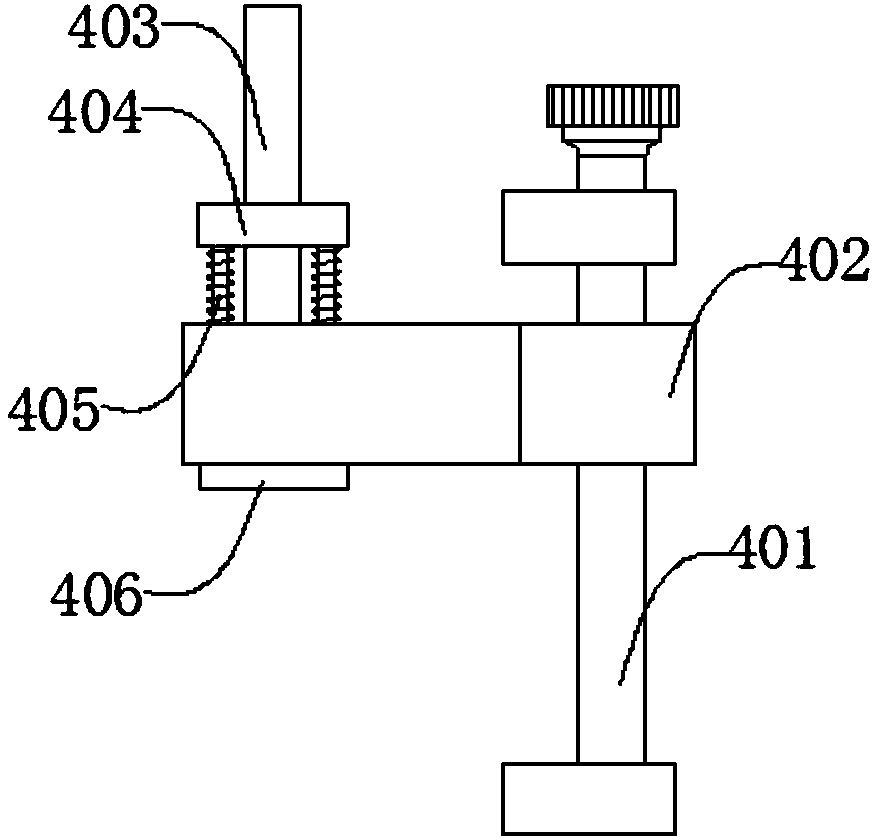
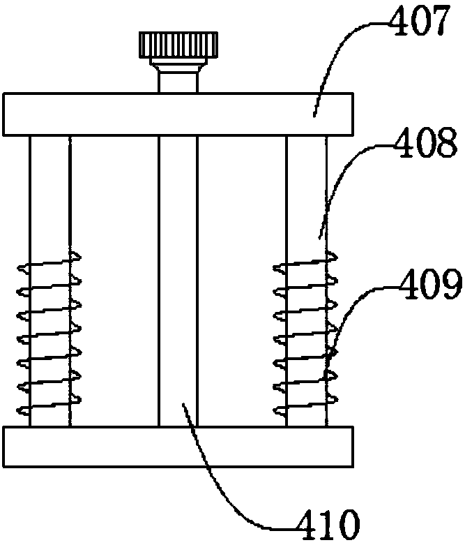
[0024] like figure 1 , figure 2 , image 3 , Figure 4 , Figure 5 , Image 6As shown, a quick clamping PCB board gluing device includes a frame 1, a door frame 2, a fixture seat 3, a positioning mechanism 4, an electromagnet 5, a cylinder 6, an upper push plate 7, a connecting rod 8, a first Spring 9, lower push plate 10, servo motor 11, leading screw 12, feed nut 13, slide seat 14, gluing mechanism 15, described portal frame 2 is positioned at frame 1 upper end, and described portal frame 2 and machine The frame 1 is connected by welding, the clamp seat 3 is located at the upper end of the frame 1, the clamp seat 3 is connected with the frame 1 by bolts, the clamp seat 3 is also provided with a positioning mechanism 4, and the positioning mechanism 4 Connected with the fixture seat 3 by bolts, the electromagnet 5 is located inside the fixture seat 3, the electromagnet 5 is connected with the fixture seat 3 by bolts, the cylinder 6 is located at the upper end of the doo...


PUM


Abstract

The invention discloses a quick-clamped PCB gluing device. The quick-clamped PCB gluing device comprises a frame, a portal, a fixture base, a positioning mechanism, an electromagnet, a cylinder, an upper push plate, a connecting rod, a first spring, a lower push plate, a servo motor, a lead screw, a feeding nut, a slide base and a gluing mechanism; the positioning mechanism further comprises an adjusting mechanism, a slide plate, a limiting rod, an upper limiting plate, a second spring and a lower limiting plate; the electromagnet is powered off; the second spring is returned to push the limiting rod to upwards move to extend outside the fixture base; a PCB to be machined is put in an area consisting of four limiting rods for positioning; the cylinder pushes the upper push plate to downwards move in place, so that the gluing mechanism is contacted with the PCB to be machined; the servo motor drives the gluing mechanism to move; the gluing mechanism glues the surface of the PCB; and after the gluing is finished, the electromagnet is electrified to suck with the lower limiting plate, so that the limiting rods are driven to downwards move to return, and operators can take away the glued PCB.

Description

technical field [0001] The invention relates to a mechanical device, in particular to a fast clamping PCB board gluing device. Background technique [0002] PCB multi-layer board refers to a multi-layer circuit board used in electrical products. Generally, it is a printed circuit board in which single-sided or double-sided boards are alternately connected together through a positioning system and insulating bonding materials, and the conductive patterns are interconnected according to design requirements. Such as four-layer and six-layer printed circuit boards, in the process of making PCB multilayer boards, it is necessary to coat the adhesive glue on the surface of the raw material board. In the existing method, a roller with bristles is often used to directly coat the glue. Since the direction of force bending when the bristles are in contact with the raw material board is uncertain, the glue absorbed on the bristles cannot be evenly coated on the surface of the raw mater...

Claims


Application Information

Patent Timeline
IPC IPC(8): B05C5/02B05C11/10B05C11/02B05C13/02
CPCB05C5/02B05C11/023B05C11/10B05C11/1047B05C13/02
Inventor 蒋华芳
Owner SUZHOU YILIHUA ELECTRONICS CO LTD
Why Eureka
Try Eureka