
A drilling jig with cleaning function

A drilling fixture and function technology, which is applied in the field of drilling fixtures with cleaning function to avoid displacement and increase clamping force.

Active Publication Date: 2019-05-10
重庆纵翼机械制造有限公司
View PDF1 Cites 0 Cited by
  • Summary
  • Abstract
  • Description
  • Claims
  • Application Information

AI Technical Summary

Problems solved by technology

[0006] The purpose of the present invention is to provide a drilling jig with a cleaning function, which is used to solve the problem of synchronously cleaning the waste generated during the drilling process of the shaft

Method used


Image

  • A drilling jig with cleaning function
  • A drilling jig with cleaning function
  • A drilling jig with cleaning function

Examples


Embodiment Construction

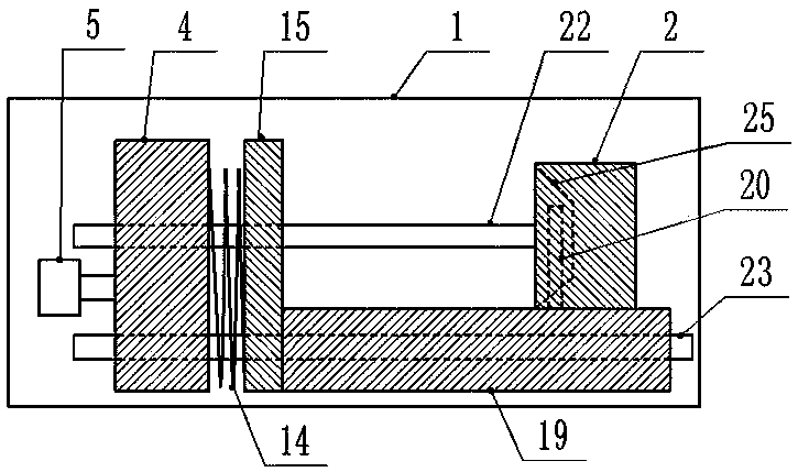
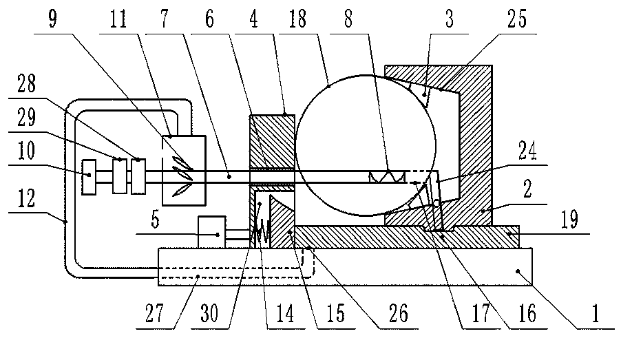
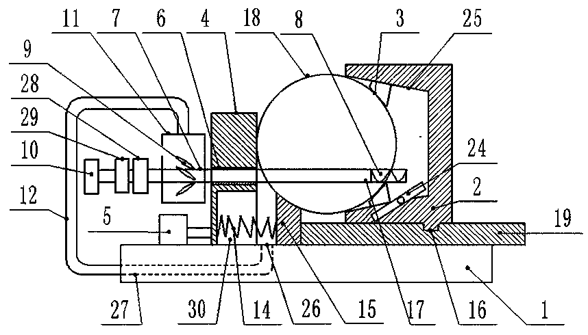
[0026] The reference signs in the drawings of the description include: base 1, V-shaped block 2, clamping pad 3, pressing slider 4, cylinder 5, drill pipe hole 6, drill pipe 7, drill bit 8, rotating blade 9, numerical control Center 10, sleeve 11, hose 12, limit arm 13, spring 14, gasket block 15, limit arm groove 16, shaft hole 17, shaft 18, ejector rod 19, drive arm 20, hinge post 21, the first A chute 22 , a second chute 23 , a rotating arm 24 , a clamping surface 25 , a collecting hole 26 , a collecting chamber 27 , a feeding device 28 , a rotating device 29 , and a groove 30 .

[0027] Such as figure 1 As shown, a drilling jig with a cleaning function includes a base 1 installed horizontally. The base 1 is provided with a first chute 22 and a second chute 23. The two chutes are parallel to each other. On the base 1, from left to right A cylinder 5, a compression slider 4, a spring 14, and a gasket block 15 are installed in sequence; a compression slider 4 is welded on th...


PUM


Abstract

The invention relates to the technical field of shaft drilling fixtures, in particular to a drilling fixture with a cleaning function. The drilling fixture comprises a base; a V-shaped block and a compressing sliding block are arranged on the base; a drill rod hole allowing a drill rod to penetrate is formed in the upper portion of the compressing sliding block; a drill bit is arranged on the side, facing the V-shaped block, of the drill rod, and the other side of the drill rod is connected with a numerical control center; a sleeve is arranged on the drill rod and internally provided with rotating blades; the rotating blades are fixedly connected to the circumferential wall of the drill rod; the sleeve communicates with a gap in the position, close to the compressing sliding block, below ashaft through a hose; a spring is arranged in the lower portion of the compressing sliding block; a seal cushion block is arranged on the spring; a jacking rod is arranged on the seal cushion block and meanwhile slidably connected to the front side face of the V-shaped block; a limiting arm groove is formed in the jacking rod; a limiting arm is further arranged on the front side face of the V-shaped cushion block; a driving arm and a shaft hole are on the same straight line; and the lower end of a long arm body of the limiting arm can be matched with the limiting arm groove. When the drillingfixture is adopted to drill the shaft, generated waste scraps can be removed synchronously.

Description

technical field [0001] The invention relates to the technical field of shaft drilling jigs, in particular to a drilling jig with a cleaning function. Background technique [0002] In machining, it is often necessary to drill the shaft. Existing shaft parts mostly use drill sleeves for positioning when drilling, and the drill sleeve is fixed on the shaft, or the shaft is fixed on the drill sleeve, so as to realize the relative fixation of the drill rod and the shaft rod. [0003] During the drilling process, the axial surface will exert a reverse force on the drill pipe. This reverse force often causes the shaft to vibrate, and then drives the entire bushing to vibrate. The surface of the shaft is arc-shaped, causing the drill fixed on the shaft to vibrate. The clamping of the sleeve and the shaft is very easy to slip, which affects the machining accuracy. [0004] In order to solve the above problems, the Chinese patent with the notification number CN106826281A discloses a...

Claims


Application Information

Patent Timeline
Patent Type & Authority Patents(China)
IPC IPC(8): B23Q3/08B23Q11/00
CPCB23Q3/08B23Q11/0046B23Q2703/04
Inventor 蒋儒章
Owner 重庆纵翼机械制造有限公司
Learn More